ENGINE UNIT REMOVAL

-
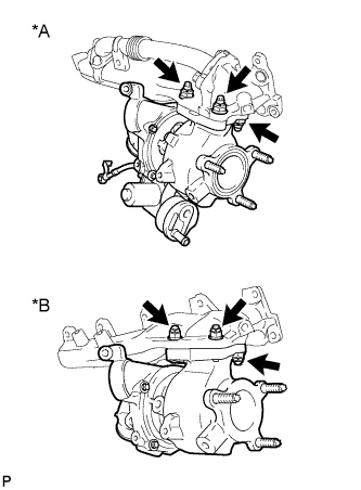
REMOVE VACUUM PUMP ASSEMBLY (w/ Intercooler)
-
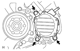
Remove the 3 bolts and vacuum pump.
-
Remove the 2 O-rings.
-
-
REMOVE NO. 1 ENGINE OIL LEVEL DIPSTICK GUIDE
-
Remove the 2 bolts and No. 1 engine oil level dipstick guide.
-
Remove the O-ring from the No. 1 engine oil level dipstick.
-
-
REMOVE NO. 1 INTAKE AIR CONNECTOR PIPE
-
Disconnect the 4 connectors.
-
Using a clip remover, detach the 5 wire harness clamps.
-
Loosen the hose clamp, and remove the bolt and No. 1 intake air connector pipe.
-
-
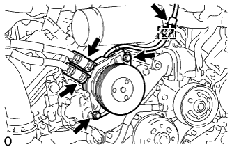
REMOVE GENERATOR ASSEMBLY
-
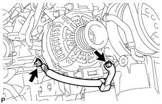
Remove the nut and bolt, and disconnect the generator positive (+) cable.
-
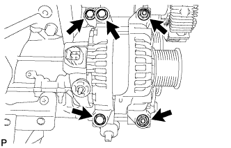
Remove the 3 bolts, 2 nuts and generator.
-
-
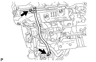
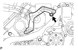
REMOVE NO. 2 VENTILATION HOSE
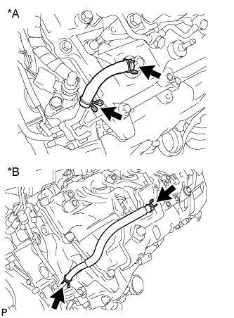
Text in Illustration *A w/ DPF *B w/o DPF -
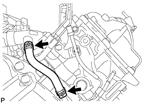
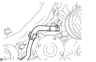
REMOVE NO. 2 TURBO WATER HOSE
-
REMOVE BREATHER PLUG RH
-
Disconnect the hose.
-
Detach the clamp and remove the breather plug RH.
-
-
REMOVE NO. 1 EXHAUST MANIFOLD HEAT INSULATOR
-
Text in Illustration *A w/ DPF *B w/o DPF Remove the 3 bolts and No. 1 exhaust manifold heat insulator.
-
-
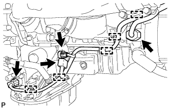
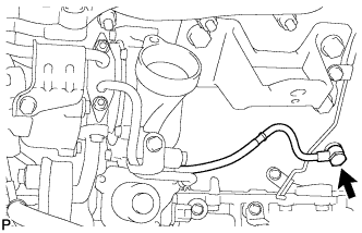
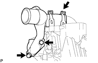
DISCONNECT NO. 1 OUTLET TURBO OIL HOSE
-
REMOVE NO. 1 TURBO WATER PIPE SUB-ASSEMBLY
-
Disconnect the water hose.
-
Remove the 3 bolts, 2 nuts, No. 1 turbo water pipe and gasket.
-
-
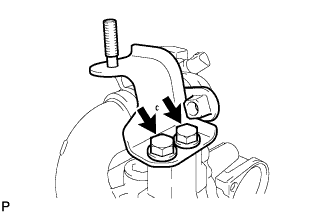
REMOVE NO. 1 TURBOCHARGER STAY
-
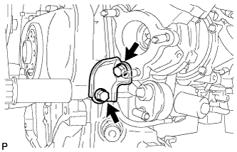
Remove the 2 bolts and No. 1 turbocharger stay.
-
-
REMOVE NO. 1 VENTILATION TUBE SUB-ASSEMBLY
-
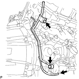
Disconnect the hose.
-
Remove the union bolt, bolt, No. 1 ventilation tube and gasket.
-
-
REMOVE NO. 1 TURBOCHARGER SUB-ASSEMBLY WITH EXHAUST MANIFOLD RH
-
Remove the union bolt and gasket, and disconnect the No. 1 inlet turbo oil pipe from the cylinder block.
-
Remove the 10 nuts, 10 collars and No. 1 turbocharger with exhaust manifold RH.
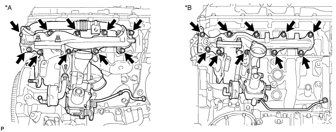
Text in Illustration *A w/ DPF *B w/o DPF -
Remove the gasket.
-
w/ DPF:
Remove the 4 bolts, No. 1 exhaust manifold pipe and 2 gaskets.
-
Remove the 2 nuts and bolt, and separate the No. 1 turbocharger and exhaust manifold RH.
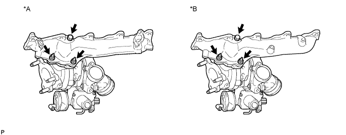
Text in Illustration *A w/ DPF *B w/o DPF -
Remove the gasket from the No. 1 turbocharger.
-
-
REMOVE NO. 3 VENTILATION HOSE
Text in Illustration *A w/ DPF *B w/o DPF -
REMOVE BREATHER PLUG LH
-
Text in Illustration *A w/ DPF *B w/o DPF Disconnect the hose.
-
w/o DPF:
Detach the clamp.
-
Remove the breather plug LH.
-
-
REMOVE NO. 2 TURBO WATER HOSE
-
REMOVE NO. 2 EXHAUST MANIFOLD HEAT INSULATOR
-
Text in Illustration *A w/ DPF *B w/o DPF Remove the 3 bolts and No. 2 exhaust manifold heat insulator.
-
-
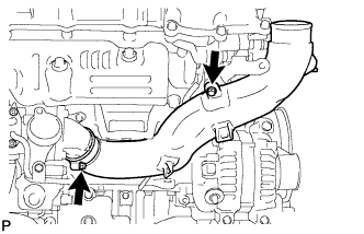
REMOVE NO. 3 TURBO WATER PIPE SUB-ASSEMBLY
-
Remove the 2 bolts, union bolt, No. 3 turbo water pipe and gasket.
-
-
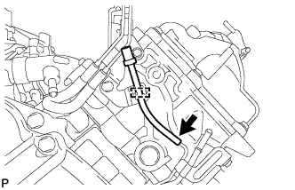
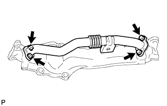
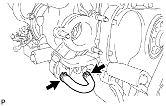
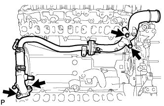
REMOVE FRONT WATER BY-PASS JOINT
-
Remove the front water by-pass joint and gasket.
-
-
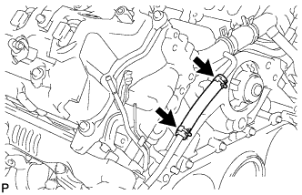
REMOVE NO. 2 TURBO WATER PIPE SUB-ASSEMBLY
-
Disconnect the water hose.
-
Remove the union bolt, bolt, No. 2 turbo water pipe and gasket.
-
-
DISCONNECT NO. 2 OUTLET TURBO OIL HOSE
-
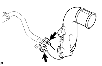
REMOVE NO. 2 TURBOCHARGER STAY
-
Remove the 2 bolts and No. 2 turbocharger stay.
-
-
REMOVE NO. 2 VENTILATION TUBE SUB-ASSEMBLY
-
Disconnect the hose.
Text in Illustration *A w/ DPF *B w/o DPF -
Remove the union bolt, bolt, No. 2 ventilation tube and gasket.
-
-
REMOVE NO. 2 TURBOCHARGER SUB-ASSEMBLY WITH EXHAUST MANIFOLD LH
-
Disconnect the 2 connectors from the turbocharger.
-
Remove the union bolt and gasket, and disconnect the No. 2 inlet turbo oil pipe from the No. 1 oil pan.
-
Remove the 10 nuts, 10 collars and No. 2 turbocharger with exhaust manifold LH.
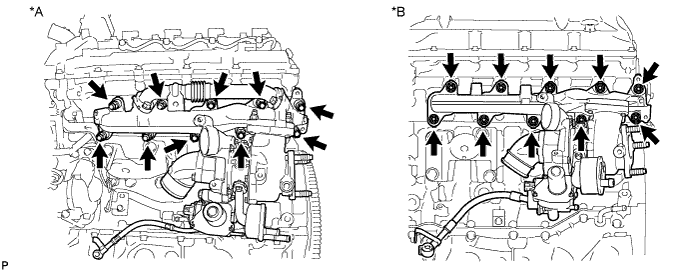
Text in Illustration *A w/ DPF *B w/o DPF -
Remove the gasket.
-
w/ DPF:
Remove the 4 bolts, No. 2 exhaust manifold pipe and 2 gaskets.
-
Text in Illustration *A w/ DPF *B w/o DPF Remove the 3 nuts, and separate the No. 2 turbocharger and exhaust manifold LH.
-
Remove the gasket from the turbocharger.
-
-
REMOVE VISCOUS HEATER ASSEMBLY WITH MAGNET CLUTCH (w/ Viscous Heater)
-
Disconnect the connector and detach the clamp.
-
Using pliers, grip the claws of the clips and slide the 2 clips.
-
Disconnect the 2 heater hoses.
-
Remove the 2 bolts and heater assembly.
-
-
REMOVE NO. 1 IDLER PULLEY BRACKET (w/ Viscous Heater)
-
Remove the bolt and No. 1 idler pulley bracket.
-
-
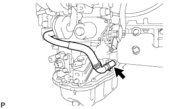
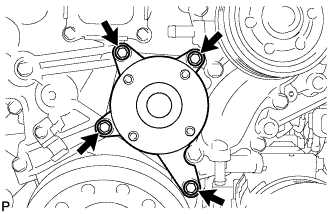
REMOVE WATER INLET
-
Disconnect the No. 2 oil cooler hose from the water pump and clamp.
-
Remove the 4 bolts and water inlet.
-
-
REMOVE THERMOSTAT
-
Remove the thermostat.
-
Remove the gasket from the thermostat.
-
-
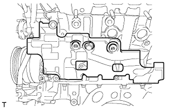
REMOVE TIMING GEAR COVER INSULATOR (w/ Intercooler)
-
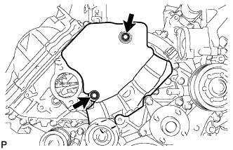
w/o Viscous Heater:
Remove the 2 bolts and timing gear cover insulator.
-
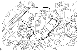
w/ Viscous Heater:
Remove the timing gear cover insulator.
-
-
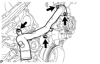
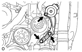
REMOVE V-RIBBED BELT TENSIONER ASSEMBLY
-
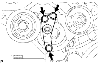
Remove the 3 bolts and V-ribbed belt tensioner bracket.
-
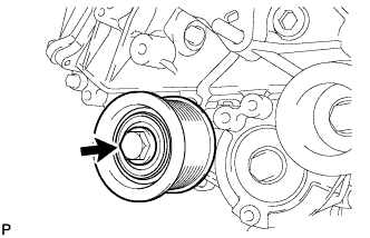
Remove the bolt and No. 1 idler pulley.
-
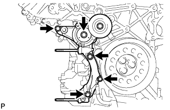
Remove the 5 bolts and V-ribbed belt tensioner.
-
-
REMOVE STARTER ASSEMBLY
-
Detach the harness clamp and disconnect the wire harness.
-
Disconnect the starter connector.
-
Remove the nut and disconnect the starter wire.
-
Disconnect the 2 starter hoses.
-
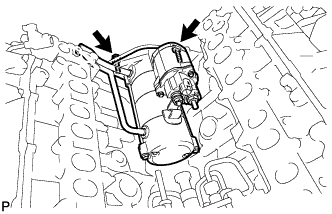
Remove the 2 bolts and starter.
-
-
REMOVE STARTER HOSE BRACKET
-
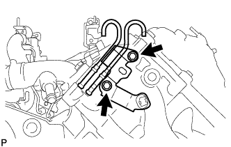
Remove the 2 bolts and starter hose bracket.
-
-
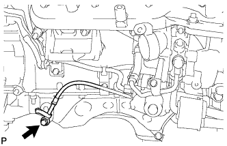
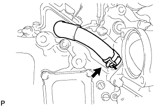
DISCONNECT INLET WATER HOSE
-
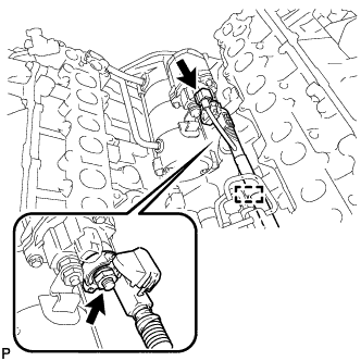
REMOVE DIESEL ENGINE COOLANT TEMPERATURE SENSOR
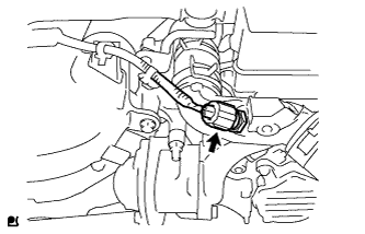
-
Disconnect the sensor connector.
-
Using a 19 mm deep socket wrench, remove the sensor and gasket.
-
-
REMOVE NO. 2 INTERCOOLER SUPPORT BRACKET
-
Remove the 2 bolts and No. 2 intercooler support bracket.
-
-
REMOVE WATER OUTLET
-
Remove the 2 bolts and gasket and disconnect the water outlet from the No. 2 water hose joint.
-
-
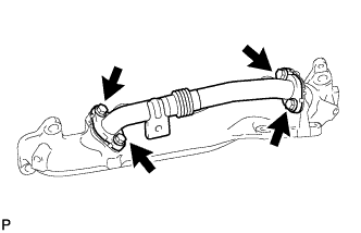
REMOVE WATER OUTLET PIPE
-
Remove the 4 bolts, water outlet pipe and 2 gaskets.
-
-
SEPARATE NO. 1 AND NO. 2 WATER OUTLET PIPES AND WATER BY-PASS OUTLET
-
Remove the 2 bolts and No. 1 water outlet pipe from the No. 2 water outlet pipe.
-
Disconnect the No. 2 water outlet pipe from the No. 1 water hose joint.
-
Disconnect the water by-pass outlet from the No. 1 water hose joint.
-
-
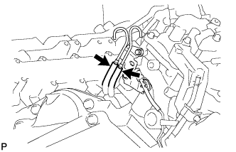
REMOVE CLUTCH FLEXIBLE HOSE BRACKET (for Manual Transmission)
-
Remove the 2 bolts and clutch flexible hose bracket.
-
-
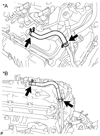
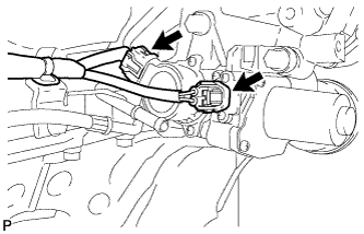
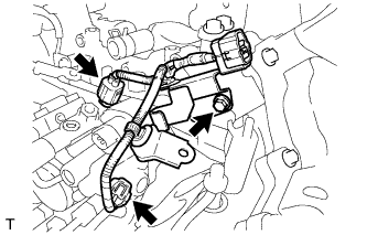
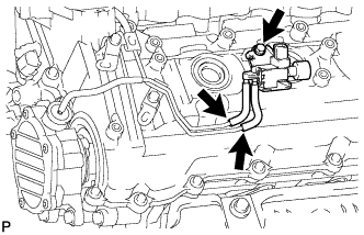
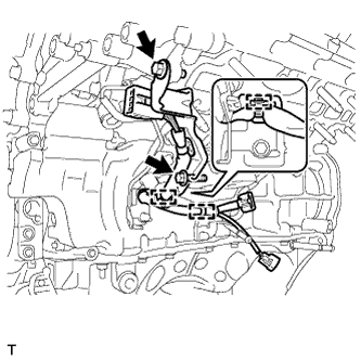
REMOVE NO. 1 GLOW PLUG CONNECTOR
-
Remove the 2 screw grommets and 2 nuts, and disconnect the 2 wire harnesses.
-
Text in Illustration *a RH *b LH Remove the 8 screw grommets, 8 nuts and 2 glow plug connectors.
-
-
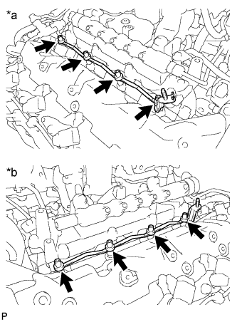
REMOVE GLOW PLUG ASSEMBLY
-
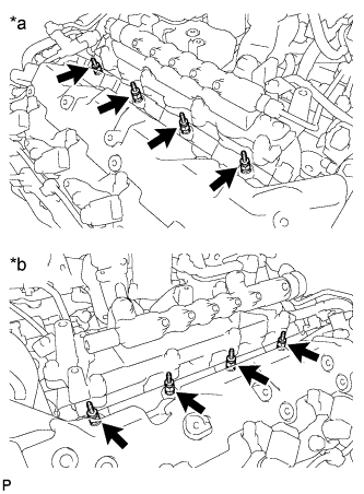
Text in Illustration *a RH *b LH Using a 10 mm deep socket wrench, remove the 8 glow plugs.
Tech Tips
Before removing the glow plugs, thoroughly clean off all dirt, sand, etc.
-
-
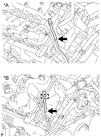
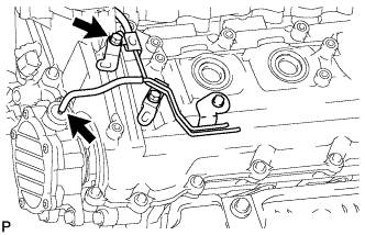
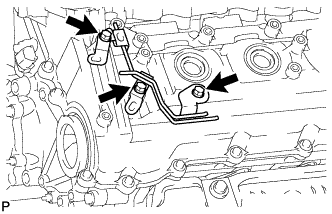
REMOVE FUEL PUMP MOTOR WIRE
-
Disconnect the 2 connectors and remove the bolt and fuel pump motor wire.
-
-
REMOVE NO. 2 IDLER PULLEY (w/ Viscous Heater)
-
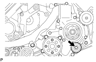
Remove the bolt, cover, No. 2 idler pulley and collar.
-
-
REMOVE NO. 2 IDLER PULLEY BRACKET (w/ Viscous Heater)
-
Remove the 3 bolts and idler pulley bracket.
-
-
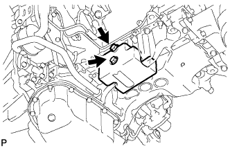
REMOVE FAN BRACKET SUB-ASSEMBLY
-
Remove the 4 bolts and fan bracket.
-
-
REMOVE NO. 1 VACUUM SWITCHING VALVE ASSEMBLY (w/o DPF)
-
Disconnect the 2 vacuum hoses.
-
Remove the bolt and vacuum switching valve.
-
-
REMOVE NO. 1 VACUUM TRANSMITTING PIPE SUB-ASSEMBLY (w/o DPF)
-
w/ Intercooler:
Disconnect the 2 vacuum hoses.
-
Remove the 3 bolts and vacuum transmitting pipe.
-
-
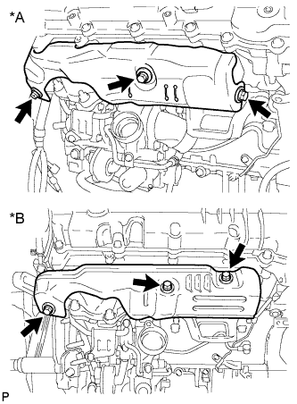
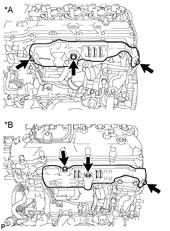
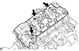
REMOVE CYLINDER HEAD COVER SILENCER RH (w/o DPF)
-
w/ Intercooler:
Remove the 3 bolts and cylinder head cover silencer RH.
-
-
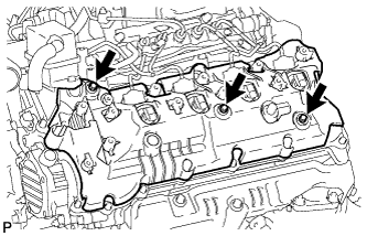
REMOVE CYLINDER HEAD COVER SILENCER LH (w/o DPF)
-
w/ Intercooler:
Remove the 3 bolts and cylinder head cover silencer LH.
-
-
REMOVE REAR CYLINDER HEAD PLATE RH (w/o EGR System)
-
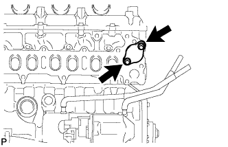
Remove the 2 bolts, rear cylinder head plate RH and gasket.
-
-
REMOVE REAR CYLINDER HEAD PLATE LH (w/o EGR System)
-
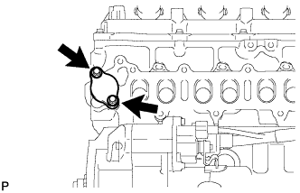
Remove the 2 bolts, rear cylinder head plate LH and gasket.
-
-
REMOVE NO. 1 INTAKE AIR CONNECTOR BRACKET
-
Remove the 2 bolts and No. 1 intake air connector bracket.
-
-
REMOVE AIR TUBE SUPPORT
-
Remove the 2 bolts and air tube support.
-
-
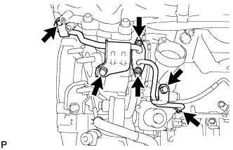
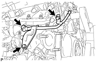
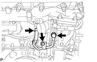
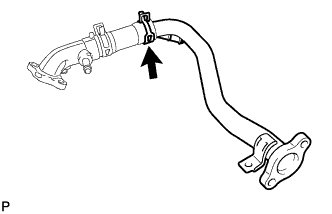
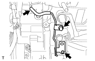
REMOVE NO. 1 WATER BY-PASS PIPE SUB-ASSEMBLY
-
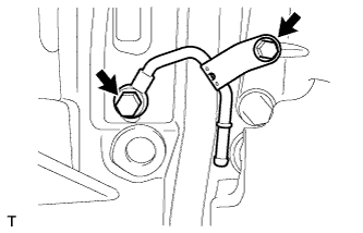
Remove the union bolt, bolt, No. 1 water by-pass pipe and gasket.
-
-
REMOVE NO. 4 VACUUM TRANSMITTING PIPE SUB-ASSEMBLY (w/ Intercooler)
-
Disconnect the vacuum hose.
-
Remove the 2 bolts and No. 4 vacuum transmitting pipe.
-
-
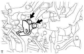
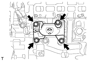
REMOVE ENGINE MOUNTING BRACKET RH
-
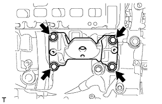
Remove the 4 bolts and engine mounting bracket RH.
-
-
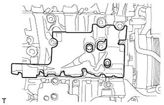
REMOVE NO. 1 CYLINDER BLOCK INSULATOR
-
REMOVE NO. 2 INTAKE AIR CONNECTOR BRACKET
-
Detach the 2 wire harness clamps.
-
Remove the bolt and No. 2 intake air connector bracket.
-
-
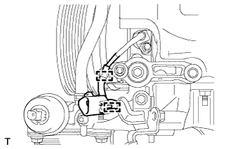
REMOVE TURBOCHARGER WIRE
-
Detach the 3 wire harness clamps.
-
Remove the 2 bolts and turbocharger wire.
-
-
REMOVE NO. 3 VACUUM TRANSMITTING PIPE SUB-ASSEMBLY
-
w/ Intercooler:
Disconnect the vacuum hose.
-
Remove the 2 bolts and No. 3 vacuum transmitting pipe.
-
-
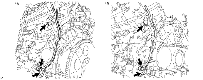
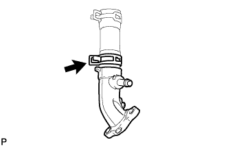
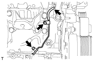
REMOVE NO. 2 WATER BY-PASS PIPE SUB-ASSEMBLY
-
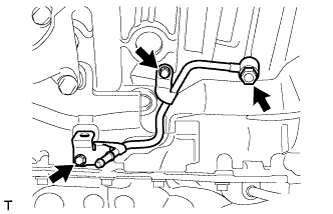
Remove the union bolt, 2 bolts, No. 2 water by-pass pipe and gasket.
-
-
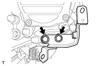
REMOVE ENGINE MOUNTING BRACKET LH
-
Remove the 4 bolts and engine mounting bracket LH.
-
-
REMOVE NO. 2 CYLINDER BLOCK INSULATOR
-
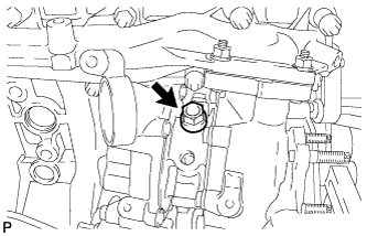
REMOVE OIL TANK BRACKET
-
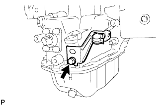
Remove the bolt and oil tank bracket.
-
-
REMOVE NO. 1 INTERCOOLER SUPPORT BRACKET
-
Remove the 2 bolts and No. 1 intercooler support bracket.
-
-
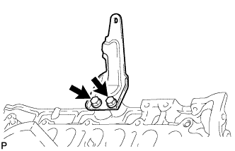
REMOVE NO. 3 ENGINE HANGER
-
Remove the 2 bolts and No. 3 engine hanger.
-
-
REMOVE OIL FILTER BRACKET DRAIN COCK ASSEMBLY
-
Remove the oil filter drain cock plug.
-
Remove the oil filter drain cock body.
Tech Tips
If the drain cock is deformed or clogged, replace or repair it.
-
-
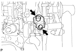
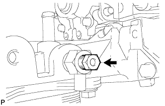
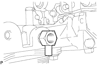
REMOVE OIL PRESSURE REGULATOR ASSEMBLY
-
Using a 26 mm wrench, remove the oil pressure regulator and gasket.
-
Remove the O-ring from the oil pressure regulator body.
-
Hold the oil pressure regulator body in a vise between aluminum plates.
Note
Be careful not to damage the oil pressure regulator body.
-
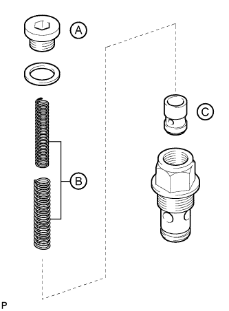
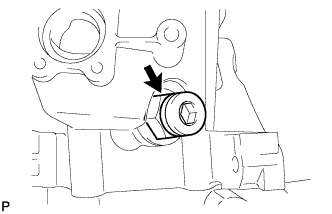
Using a 10 mm hexagon wrench, remove the oil pump relief valve plug labeled A and gasket.
CAUTION:
When removing the plug, be careful as the spring will be jumped out.
-
Remove the 2 springs labeled B.
-
Remove the oil pump relief valve labeled C.
-
-
REMOVE STIFFENER INSULATOR RH (w/ Intercooler)
-
Remove the 2 bolts and stiffener insulator RH.
-
-
SET NO. 1 CYLINDER TO TDC/COMPRESSION
-
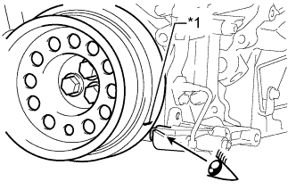
Text in Illustration *1 Timing Mark Align the timing mark of the crankshaft pulley and the chain cover and compressor bracket.
-
-
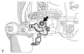
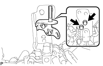
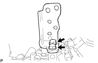
REMOVE COMPRESSOR BRACKET
-
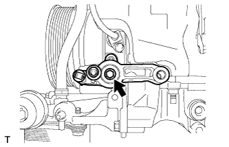
Remove the bolt and compressor bracket.
-
-
REMOVE EXHAUST FUEL ADDITION INJECTOR ASSEMBLY (w/ DPF)
-
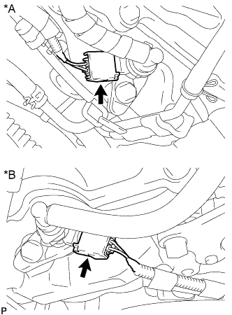
Text in Illustration *A for Bank 1 *B for Bank 2 Disconnect the 2 exhaust fuel addition injector connectors.
-
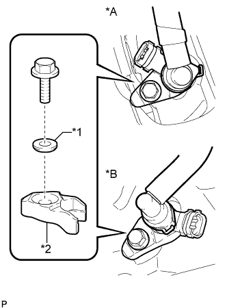
Text in Illustration *A for Bank 1 *B for Bank 2 *1 Washer *2 Nozzle Holder Clamp Remove the 2 bolts, 2 washers and 2 nozzle holder clamps.
-
Remove the 2 exhaust fuel addition injectors and 2 gaskets.
-
-
REMOVE FUEL INJECTOR SEAL (w/ DPF)
-
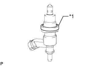
Text in Illustration *1 Fuel Injector Seal Remove the 2 fuel injector seals.
-
-
REPLACE FLYWHEEL RING GEAR
CAUTION:
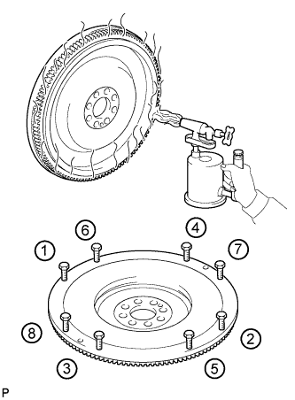
When torching the flywheel:
-
Wear protective gloves.
-
Be careful as the flywheel is hot.
Tech Tips
If the flywheel ring gear is deformed or the gear teeth are damaged, replace it.
-
Using a torch, heat the ring gear evenly to approximately 200°C (392°F).
-
Install 8 10 mm x 1.25 pitch bolts with a length of 70 mm or more to the flywheel.
-
Uniformly tighten the 8 bolts in the order shown in the illustration.
-
Remove the ring gear from the flywheel.
-
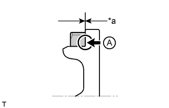
Text in Illustration *a No Clearance Using a torch, heat a new ring gear evenly to approximately 200°C (392°F).
Note
Be careful not to overheat the ring gear.
-
Using a brass bar, tap the ring gear onto the flywheel with its chamfered gear teeth facing the block.
Note
-
Make sure to press in the ring gear until the ring gear contacts the flywheel, as shown in A in the illustration.
-
After installing, allow the ring gear to cool before handling.
-
-
-
REPLACE FLYWHEEL STRAIGHT PIN
Tech Tips
It is not necessary to remove the straight pin unless it is being replaced.
-
Replace the flywheel straight pin.
-