CYLINDER HEAD GASKET INSTALLATION

-
INSPECT CYLINDER HEAD SET BOLT
-
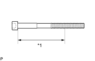
Text in Illustration *1 Measuring Point Using a vernier caliper, measure the diameter of the elongated thread at the measuring point.
Measuring point 94 mm (3.70 in.) for intake side bolt 89 mm (3.50 in.) for exhaust side bolt Standard diameter 10.85 to 11.00 mm (0.427 to 0.433 in.) Minimum diameter 10.6 mm (0.417 in.) If the diameter is less than the minimum, replace the cylinder head bolt.
Tech Tips
If a visual check reveals no excessively thin areas, check the center of the bolt (see illustration) and find the area that has the smallest diameter.
-
-
INSPECT CYLINDER HEAD SUB-ASSEMBLY
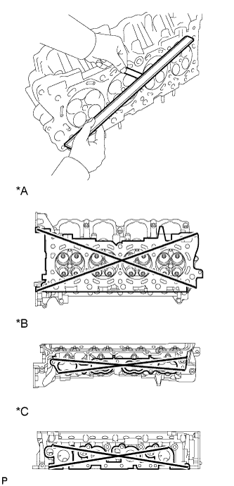
Text in Illustration *A Cylinder Head Lower Side *B Intake Side *C Exhaust Side
-
Using a precision straightedge and feeler gauge, measure the warpage of the surfaces where the cylinder head contacts the cylinder block and manifold.
Standard Warpage Item Specified Condition Cylinder head lower side 0.05 mm (0.00197 in.) Intake side 0.08 mm (0.00315 in.) Exhaust side 0.05 mm (0.00197 in.) Maximum warpage 0.10 mm (0.00394 in.) If the warpage is more than the maximum, replace the cylinder head.
-
Using a dye penetrant, check the intake ports, exhaust ports and cylinder surface for cracks.
If cracked, replace the cylinder head.
-
-
INSTALL CYLINDER HEAD SUB-ASSEMBLY RH
-
Clean the cylinder block with solvent.
-
Set the piston of the No. 1 cylinder to slightly ATDC.
-
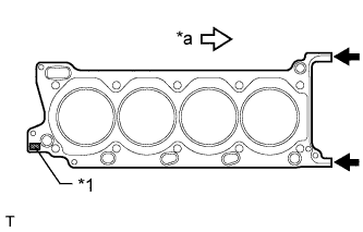
Text in Illustration *1 Lot No. *a Front Place the cylinder head gasket on the cylinder block surface with the front face of the Lot No. stamp upward.
Note
-
Be careful of the installation direction.
-
Make sure that no oil is on the front end (indicated by the arrows) of the cylinder head gasket.
-
-
Place the cylinder head on the cylinder block.
Note
-
Ensure that no oil is on the mounting surface of the cylinder head.
-
Gently place the cylinder head in order not to damage the gasket with the bottom part of the head.
Tech Tips
The cylinder head bolts are tightened in 3 progressive steps.
-
-
Apply a light coat of engine oil to the threads and under the heads of the cylinder head bolts.
-
Step 1:
-
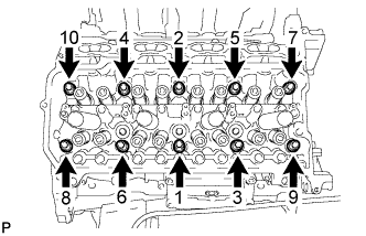
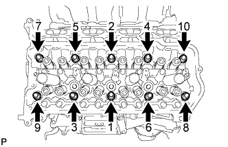
Using a 10 mm bi-hexagon wrench, install and uniformly tighten the 10 cylinder head bolts with the plate washers in several steps in the sequence shown in the illustration.
- Torque:
- 36 N*m { 367 kgf*cm, 27 ft.*lbf }
-
-
Step 2:
-
Mark the front side of each cylinder head bolt head with paint.
-
Tighten the cylinder head bolts another 90°.
-
-
Step 3:
-
Tighten the cylinder head bolts an additional 90°.
-
Check that the paint marks are now at a 180° angle to the front.
-
-
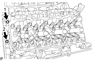
Install and uniformly tighten the 2 bolts in the sequence shown in the illustration.
- Torque:
- 21 N*m { 214 kgf*cm, 15 ft.*lbf }
-
-
INSTALL CYLINDER HEAD SUB-ASSEMBLY LH
-
Clean the cylinder block with solvent.
-
Set the piston of the No. 1 cylinder to slightly ATDC.
-
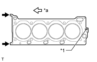
Text in Illustration *1 Lot No. *a Front Place the cylinder head gasket on the cylinder block surface with the front face of the Lot No. stamp upward.
Note
-
Be careful of the installation direction.
-
Make sure that no oil is on the front end (indicated by the arrows) of the cylinder head gasket.
-
-
Place the cylinder head on the cylinder block.
Note
-
Ensure that no oil is on the mounting surface of the cylinder head.
-
Gently place the cylinder head in order not to damage the gasket with the bottom part of the head.
Tech Tips
The cylinder head bolts are tightened in 3 progressive steps.
-
-
Apply a light coat of engine oil to the threads and under the heads of the cylinder head bolts.
-
Step 1:
Tech Tips
The cylinder head bolts are tightened in 3 progressive steps.
-
Using a 10 mm bi-hexagon wrench, install and uniformly tighten the 10 cylinder head bolts with the plate washers in several steps in the sequence shown in the illustration.
- Torque:
- 36 N*m { 367 kgf*cm, 27 ft.*lbf }
-
-
Step 2:
-
Mark the front side of each cylinder head bolt head with paint.
-
Tighten the cylinder head bolts another 90°.
-
-
Step 3:
-
Tighten the cylinder head bolts an additional 90°.
-
Check that the paint marks are now at a 180° angle to the front.
-
-
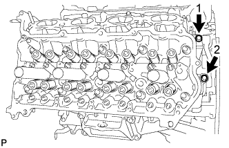
Install and uniformly tighten the 2 bolts in the sequence shown in the illustration.
- Torque:
- 21 N*m { 214 kgf*cm, 15 ft.*lbf }
-
-
INSTALL VALVE STEM CAP
-
Apply a light coat of engine oil to the valve stem caps.
-
Install the 32 valve stem caps to the cylinder heads.
-
-
INSTALL VALVE LASH ADJUSTER ASSEMBLY
-
Inspect the valve lash adjuster before installing it Click here.
-
Install the 32 valve lash adjusters to the cylinder heads.
Note
Install the lash adjuster to the same place it was removed from.
-
-
INSTALL NO. 1 VALVE ROCKER ARM SUB-ASSEMBLY
-
Apply engine oil to the lash adjuster tips and valve stem cap ends.
-
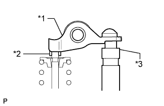
Text in Illustration *1 Valve Rocker Arm *2 Valve Stem Cap *3 Valve Lash Adjuster Install the 32 valve rocker arms as shown in the illustration.
-
-
INSTALL CAMSHAFT
-
INSTALL EXHAUST MANIFOLD SUB-ASSEMBLY