CYLINDER HEAD GASKET INSTALLATION

-
INSTALL NO. 2 CYLINDER HEAD GASKET
-
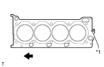
Text in Illustration *1 Lot No. 
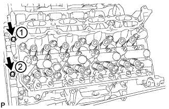
Engine Front Place a new cylinder head gasket on the cylinder block surface with the front face of the Lot No. stamp upward.
Note
-
Make sure that the gasket is installed facing the proper direction.
-
Make sure that no oil is on the front end (indicated by the arrows) of the No. 2 cylinder head gasket.
-
-
-
INSTALL CYLINDER HEAD SUB-ASSEMBLY LH
-
Place the cylinder head on the cylinder block.
Note
-
Make sure that no oil is on the mounting surface of the cylinder head.
-
Place the cylinder head gently in order not to damage the gasket with the bottom part of the head.
-
-
Install the cylinder head bolts.
Tech Tips
The cylinder head bolts are tightened in 3 progressive steps.
-
Apply a light coat of engine oil to the threads and under the heads of the cylinder head bolts.
-
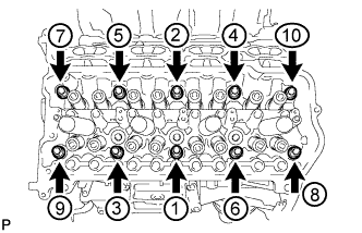
Step 1:
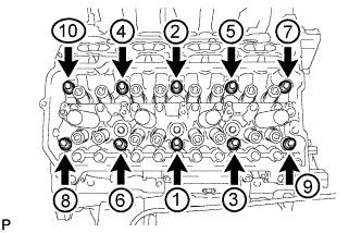
Using a 10 mm bi-hexagon wrench, install and uniformly tighten the 10 cylinder head bolts with the plate washers in several steps in the sequence shown in the illustration.
- Torque:
- 36 N*m { 367 kgf*cm, 27 ft.*lbf }
-
Mark the front side of each cylinder head bolt head with paint.
-
Step 2:
Tighten the cylinder head bolts 90°.
-
Step 3:
Tighten the cylinder head bolts an additional 90°.
-
Check that the paint marks are now at a 180° angle to the front.
-
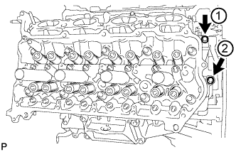
Install and uniformly tighten the 2 bolts in the sequence shown in the illustration.
- Torque:
- 21 N*m { 214 kgf*cm, 15 ft.*lbf }
Note
Thoroughly wipe clean any seal packing.
-
-
-
INSTALL CYLINDER HEAD GASKET
-
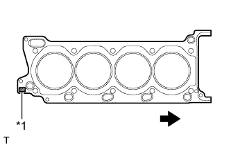
Text in Illustration *1 Lot No. Engine Front Place a new cylinder head gasket on the cylinder block surface with the front face of the Lot No. stamp upward.
Note
-
Make sure that the gasket is installed facing the proper direction.
-
Make sure that no oil is on the front end (indicated by the arrows) of the cylinder head gasket.
-
-
-
INSTALL CYLINDER HEAD SUB-ASSEMBLY
-
Place the cylinder head on the cylinder block.
Note
-
Place the cylinder head gently in order not to damage the gasket with the bottom part of the head.
-
Make sure that no oil is on the mounting surface of the cylinder head.
-
-
Install the cylinder head bolts.
Tech Tips
The cylinder head bolts are tightened in 3 progressive steps.
-
Apply a light coat of engine oil to the threads and under the heads of the cylinder head bolts.
-
Step 1:
Using a 10 mm bi-hexagon wrench, install and uniformly tighten the 10 cylinder head bolts with the plate washers in several steps in the sequence shown in the illustration.
- Torque:
- 36 N*m { 367 kgf*cm, 27 ft.*lbf }
-
Mark the front side of each cylinder head bolt head with paint.
-
Step 2:
Tighten the cylinder head bolts 90°.
-
Step 3:
Tighten the cylinder head bolts an additional 90°.
-
Check that the paint marks are now at a 180° angle to the front.
-
Install and uniformly tighten the 2 bolts in the sequence shown in the illustration.
- Torque:
- 21 N*m { 214 kgf*cm, 15 ft.*lbf }
Note
Thoroughly wipe clean any seal packing.
-
-
-
INSTALL VALVE STEM CAP
-
Apply a light coat of engine oil to the valve stem caps.
-
Install the 32 valve stem caps to the cylinder head.
-
-
INSTALL VALVE LASH ADJUSTER ASSEMBLY
-
Inspect the valve lash adjusters Click here.
-
Install the 32 valve lash adjusters to the cylinder head.
Note
Install each valve lash adjuster to the same place it was removed from.
-
-
INSTALL NO. 1 VALVE ROCKER ARM SUB-ASSEMBLY
-
Apply engine oil to the valve lash adjuster tips and valve stem cap ends.
-
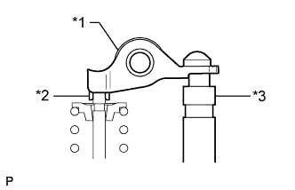
Text in Illustration *1 No. 1 Valve Rocker Arm *2 Valve Stem Cap *3 Valve Lash Adjuster Install the 32 No. 1 valve rocker arms as shown in the illustration.
-
-
INSTALL CAMSHAFT SUB-ASSEMBLY
-
INSTALL EXHAUST MANIFOLD ASSEMBLY