ENGINE UNIT INSTALLATION

-
INSTALL FLYWHEEL RING GEAR (for Manual Transmission)
-
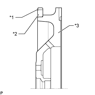
Text in Illustration *1 Chamfer *2 Ring Gear *3 Flywheel Using a torch, heat the ring gear evenly to approximately 200°C (392°F).
Note
Be careful not to overheat the ring gear.
-
Using a brass bar, tap the ring gear onto the flywheel with its chamfered gear teeth facing the block.
Note
After installing, allow the ring gear to cool before handling.
-
-
INSTALL FRONT NO. 1 ENGINE MOUNTING BRACKET RH
-
Install the front No. 1 engine mounting bracket RH with the 4 bolts.
- Torque:
- 43 N*m { 438 kgf*cm, 32 ft.*lbf }
-
-
INSTALL FRONT NO. 1 ENGINE MOUNTING BRACKET LH
-
Install the front No. 1 engine mounting bracket LH with the 3 bolts.
- Torque:
- 43 N*m { 438 kgf*cm, 32 ft.*lbf }
-
-
INSTALL ENGINE OIL LEVEL DIPSTICK GUIDE
-
Text in Illustration *1 New O-Ring Install a new O-ring to the engine oil level dipstick guide.
-
Apply a light coat of engine oil to the O-ring.
-
Push the engine oil level dipstick guide end into the guide hole.
-
Install the engine oil level dipstick guide with the bolt.
- Torque:
- 10 N*m { 102 kgf*cm, 7 ft.*lbf }
-
Install the engine oil level dipstick.
-
-
INSTALL V-RIBBED BELT TENSIONER ASSEMBLY
-
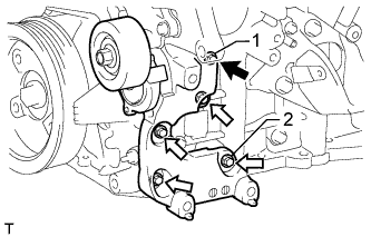
Temporarily install the V-ribbed belt tensioner with the 5 bolts.
Standard Bolt Item Length A 70 mm (2.76 in.) B 33 mm (1.30 in.) Text in Illustration 
Bolt A 
Bolt B -
Tighten bolts 1 and 2 in numerical order.
- Torque:
- 36 N*m { 367 kgf*cm, 27 ft.*lbf }
-
Tighten the other bolts.
- Torque:
- 36 N*m { 367 kgf*cm, 27 ft.*lbf }
-
-
INSTALL NO. 2 IDLER PULLEY SUB-ASSEMBLY
-
Install the 2 No. 2 idler pulleys with the 2 bolts.
- Torque:
- 54 N*m { 551 kgf*cm, 40 ft.*lbf }
-
-
INSTALL NO. 1 IDLER PULLEY SUB-ASSEMBLY
-
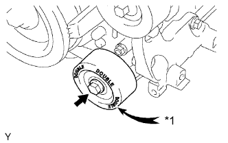
Text in Illustration *1 DOUBLE Install the No. 1 idler pulley with the bolt.
- Torque:
- 54 N*m { 551 kgf*cm, 40 ft.*lbf }
Tech Tips
"DOUBLE" is marked on the No. 1 idler pulley to distinguish it from the No. 2 idler pulley.
-
-
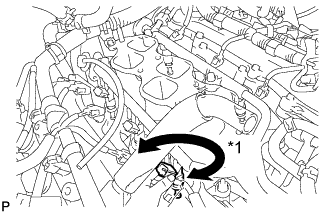
INSTALL WATER BY-PASS PIPE SUB-ASSEMBLY
-
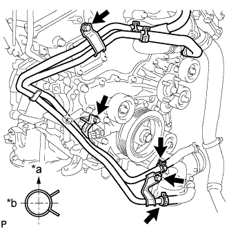
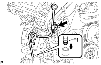
Text in Illustration *a Upward *b Rearward Install the water by-pass pipe with the 3 bolts.
- Torque:
- 10 N*m { 102 kgf*cm, 7 ft.*lbf }
-
Connect the 2 hoses.
Tech Tips
The direction of the hose clamp is indicated in the illustration.
-
-
INSTALL INTAKE MANIFOLD
-
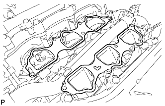
Set a new gasket on each cylinder head.
Note
-
Align the port holes of the gasket and cylinder head.
-
Be careful of the installation direction.
-
-
Set the intake manifold on the cylinder heads.
-
Install and uniformly tighten the 6 bolts and 4 nuts in several passes.
- Torque:
- 21 N*m { 214 kgf*cm, 15 ft.*lbf }
Tech Tips
Tighten the inner installation bolts of the intake manifold before tightening the outer bolts.
-
-
INSTALL FUEL INJECTOR ASSEMBLY
-
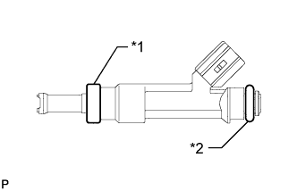
Text in Illustration *1 New Insulator *2 New O-Ring Install a new insulator to each fuel injector.
-
Apply a light coat of spindle oil or gasoline to new O-rings and install one to each fuel injector.
-
Install the 6 injectors.
-
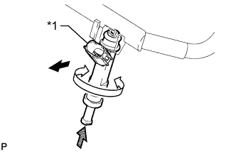
Text in Illustration *1 Connector Outward Turn 
Push While turning each fuel injector left and right, install it to the fuel delivery pipe.
-
Position the fuel injectors with the connectors facing outward.
-
-
-
INSTALL FUEL DELIVERY PIPE SUB-ASSEMBLY
-
Place the fuel delivery pipe together with the 6 fuel injectors on the intake manifold.
-
Temporarily install the 4 bolts, which are used to hold the fuel delivery pipe in place, to the intake manifold.
-
Text in Illustration *1 Turn Check that the fuel injectors rotate smoothly.
If the fuel injectors do not rotate smoothly, replace the O-ring of any injector that does not rotate smoothly.
-
Position the fuel injectors with the connectors facing outward.
-
Tighten the 4 bolts.
- Torque:
- 21 N*m { 214 kgf*cm, 15 ft.*lbf }
-
Connect the 6 fuel injector connectors.
-
-
INSTALL FUEL PIPE SUB-ASSEMBLY
-
Install the No. 1 fuel pipe and No. 2 fuel pipe with the 2 bolts.
- Torque:
- 9.0 N*m { 92 kgf*cm, 80 in.*lbf }
-
Connect the 2 fuel pipes Click here.
-
-
INSTALL IGNITION COIL ASSEMBLY
-
Install the 6 ignition coils with the 6 bolts.
- Torque:
- 10 N*m { 102 kgf*cm, 7 ft.*lbf }
-
Connect the 6 ignition coil connectors.
-
-
INSTALL NO. 2 EMISSION CONTROL VALVE SET (w/ Secondary Air Injection System)
-
Install the No. 2 emission control valve set with the 3 nuts.
- Torque:
- 21 N*m { 214 kgf*cm, 15 ft.*lbf }
-
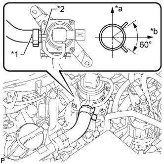
Text in Illustration *1 Paint Mark *2 Rib *a Top *b LH Side Align the paint mark with the rib and connect the No. 1 air hose.
Tech Tips
Make sure the direction of the hose clamp is as shown in the illustration.
-
Connect the No. 2 emission control valve set connector.
-
-
INSTALL NO. 1 EMISSION CONTROL VALVE SET (w/ Secondary Air Injection System)
-
Install the No. 1 emission control valve set with the 3 nuts.
- Torque:
- 21 N*m { 214 kgf*cm, 15 ft.*lbf }
-
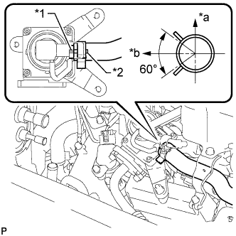
Text in Illustration *1 Rib *2 Paint Mark *a RH Side *b Top Align the paint mark with the rib and connect the No. 1 air hose.
Tech Tips
Make sure the direction of the hose clamp is as shown in the illustration.
-
Connect the No. 1 emission control valve set connector.
-
-
INSTALL HEATER WATER HOSE ASSEMBLY
-
Install the heater water hose assembly and connect the 2 hoses with the 2 bolts.
- Torque:
- 9.8 N*m { 100 kgf*cm, 87 in.*lbf }
-
-
INSTALL ENGINE WIRE