ENGINE UNIT REMOVAL

-
REMOVE ENGINE WIRE
-
DISCONNECT HEATER WATER HOSE ASSEMBLY
-
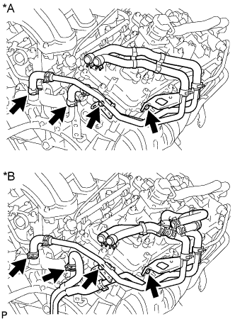
Text in Illustration *A w/o ATF Warmer *B w/ ATF Warmer Remove the 2 bolts and disconnect the 2 water hoses.
-
-
REMOVE NO. 1 EMISSION CONTROL VALVE SET (w/ Secondary Air Injection System)
-
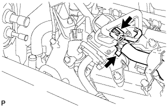
Disconnect the No. 1 emission control valve set connector.
-
Disconnect the No. 1 air hose from the No. 1 emission control valve set.
-
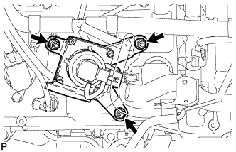
Remove the 3 nuts and No. 1 emission control valve set.
-
-
REMOVE NO. 2 EMISSION CONTROL VALVE SET (w/ Secondary Air Injection System)
-
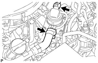
Disconnect the No. 2 emission control valve set connector.
-
Disconnect the No. 3 air hose.
-
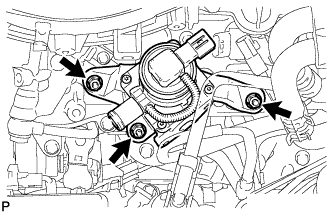
Remove the 3 nuts and No. 2 emission control valve set.
-
-
REMOVE IGNITION COIL ASSEMBLY
-
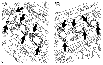
Text in Illustration *A Bank 1 *B Bank 2 Disconnect the 6 ignition coil connectors.
-
Remove the 6 bolts and 6 ignition coils.
-
-
REMOVE FUEL PIPE SUB-ASSEMBLY
-
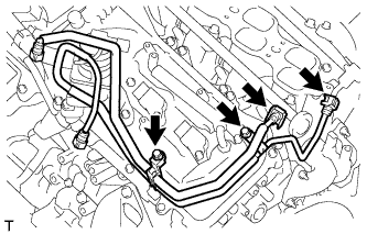
Disconnect the 2 fuel pipes Click here.
-
Remove the 2 bolts and No. 1 and No. 2 fuel pipes.
-
-
REMOVE FUEL DELIVERY PIPE SUB-ASSEMBLY
-
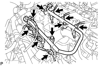
Disconnect the 6 fuel injector connectors.
-
Remove the 4 bolts and fuel delivery pipe together with the 6 fuel injectors.
Note
Be careful not to drop the injectors when removing the fuel delivery pipe.
-
-
REMOVE FUEL INJECTOR ASSEMBLY
-
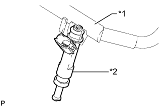
Text in Illustration *1 Fuel Delivery Pipe *2 Fuel Injector Remove the 6 fuel injectors from the fuel delivery pipe.
-
Remove the O-ring and injector vibration insulator from each fuel injector.
-
-
REMOVE INTAKE MANIFOLD
-
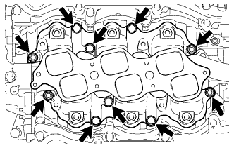
Remove the 4 nuts, 6 bolts and 2 gaskets.
-
-
REMOVE WATER BY-PASS PIPE SUB-ASSEMBLY
-
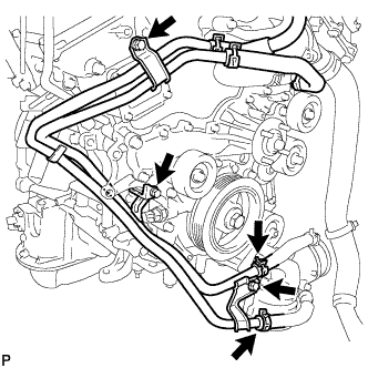
Disconnect the 2 hoses.
-
Remove the 3 bolts and water by-pass pipe.
-
-
REMOVE NO. 1 IDLER PULLEY SUB-ASSEMBLY
-
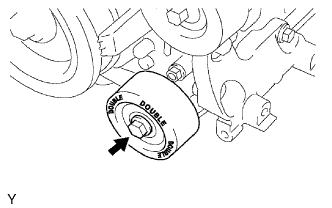
Remove the bolt and No. 1 idler pulley.
-
-
REMOVE NO. 2 IDLER PULLEY SUB-ASSEMBLY
-
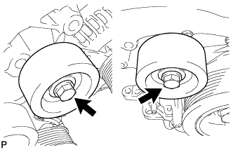
Remove the 2 bolts and 2 No. 2 idler pulleys.
-
-
REMOVE V-RIBBED BELT TENSIONER ASSEMBLY
-
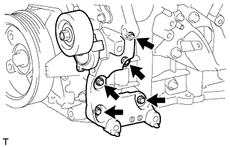
Remove the 5 bolts and V-ribbed belt tensioner.
-
-
REMOVE ENGINE OIL LEVEL DIPSTICK GUIDE
-
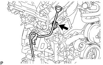
Remove the engine oil level dipstick.
-
Remove the bolt and engine oil level dipstick guide.
-
Remove the O-ring from the engine oil level dipstick guide.
-
-
REMOVE FRONT NO. 1 ENGINE MOUNTING BRACKET LH
-
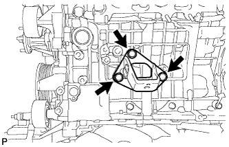
Remove the 3 bolts and front No. 1 engine mounting bracket LH.
-
-
REMOVE FRONT NO. 1 ENGINE MOUNTING BRACKET RH
-
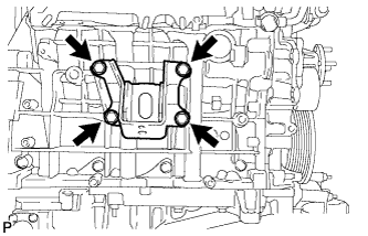
Remove the 4 bolts and front No. 1 engine mounting bracket RH.
-
-
REMOVE FLYWHEEL RING GEAR (for Manual Transmission)
Tech Tips
If the flywheel ring gear is deformed or the gears are damaged, replace it.
CAUTION:
Wear protective gloves. Hot areas on the flywheel ring gear may injure your hands.
-
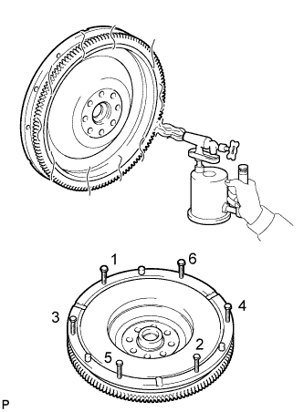
Using a torch, heat the ring gear evenly to approximately 200°C (392°F).
-
Temporarily install 6 bolts (8 mm (0.315 in.) x 1.25 pitch) with a length of 70 mm (2.76 in.) or more to the flywheel.
-
Uniformly tighten the 6 bolts in the order shown in the illustration.
-
Remove the ring gear from the flywheel.
-