REAR CRANKSHAFT OIL SEAL INSTALLATION

-
INSTALL REAR CRANKSHAFT OIL SEAL
-
Apply MP grease to the lip of a new oil seal.
-
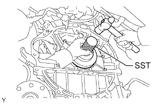
Using SST and a hammer, tap in the oil seal until its surface is flush with the rear oil seal retainer edge.
- SST
- 09223-78010
Note
-
Keep the lip free from foreign matter.
-
Do not tap the oil seal at an angle.
-
-
INSTALL DRIVE PLATE AND RING GEAR SUB-ASSEMBLY (for Automatic Transmission)
-
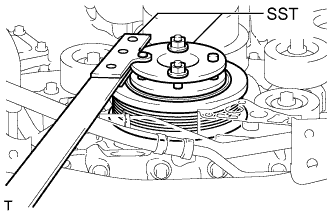
Using SST, hold the crankshaft.
- SST
- 09213-54015 ( 91651-60855 )
- 09330-00021
-
Clean the bolts and their installation holes.
-
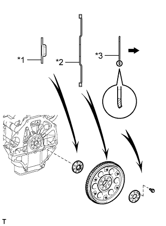
Text in Illustration *1 Front Spacer *2 Drive Plate and Ring Gear *3 Rear Spacer 
Automatic Transmission Side Install the front spacer, drive plate and rear spacer to the crankshaft.
Tech Tips
As the front spacer, the drive plate and ring gear, and the rear spacer are not reversible, be sure to install them in the direction shown in the illustration.
-
Apply adhesive to 2 or 3 threads at the end of the 8 new bolts.
Adhesive Toyota Genuine Adhesive 1324, Three Bond 1324 or equivalent -
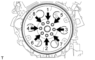
Uniformly install and tighten the 8 bolts in several steps in the sequence shown in the illustration.
- Torque:
- 83 N*m { 846 kgf*cm, 61 ft.*lbf }
Note
Do not start the engine for at least 1 hour after installing.
-
-
INSTALL FLYWHEEL SUB-ASSEMBLY (for Manual Transmission)
-
Using SST, hold the crankshaft.
- SST
- 09213-54015 ( 91651-60855 )
- 09330-00021
-
Clean the bolts and their installation holes.
-
Temporarily install the flywheel with 8 new bolts.
-
Install and tighten the 8 bolts uniformly in several steps.
- Torque:
- 30 N*m { 306 kgf*cm, 22 ft.*lbf }
-
Mark the top of the bolts with paint.
-
Tighten the 8 bolts 90° in the same sequence.
-
Check that the paint marks are now at a 90° angle to the top.
-
-
INSTALL CLUTCH DISC ASSEMBLY (for Manual Transmission)
-
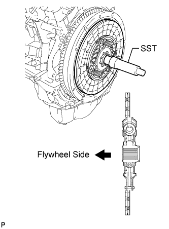
Insert SST into the clutch disc, then insert the clutch disc into the flywheel.
- SST
- 09301-00110
Note
Take care not to insert the clutch disc in the wrong direction.
-
-
INSTALL CLUTCH COVER ASSEMBLY (for Manual Transmission)
-
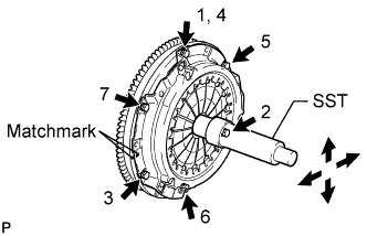
Align the matchmark on the clutch cover with the one on the flywheel.
-
In the order shown in the illustration, temporarily install the 6 bolts starting from the bolt located near the knock pin on the top.
-
Check that the disc is in the center by lightly moving SST up and down, and left and right.
- SST
- 09301-00110
-
Evenly tighten the bolts by following the order shown in the illustration.
- Torque:
- 19 N*m { 195 kgf*cm, 14 ft.*lbf }
-
-
INSPECT AND ADJUST CLUTCH COVER ASSEMBLY (for Manual Transmission)
-
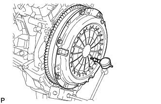
Using a dial indicator with a roller instrument, check the diaphragm spring tip alignment.
Maximum Misalignment 1.3 mm (0.0512 in.) -
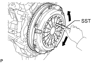
If the alignment is not as specified, adjust the diaphragm spring tip alignment using SST.
- SST
- 09333-00013
-
-
INSTALL AUTOMATIC TRANSMISSION ASSEMBLY (for Automatic Transmission)
-
INSTALL MANUAL TRANSMISSION ASSEMBLY (for Manual Transmission)