CAMSHAFT INSTALLATION

-
INSPECT CAMSHAFT TIMING GEAR ASSEMBLY
-
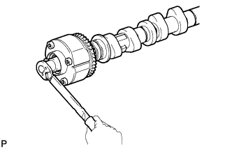
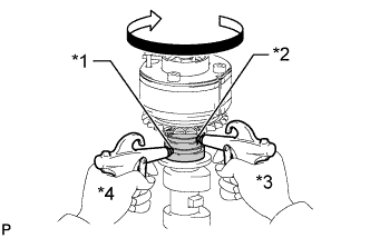
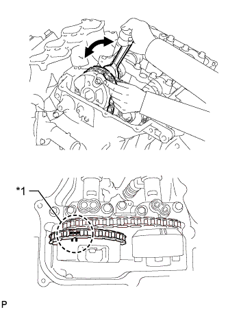
Fix the camshaft in place.
Note
Be careful not to damage the camshaft.
-
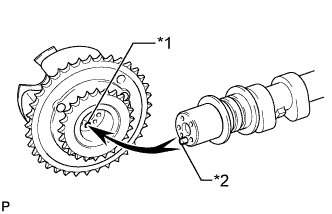
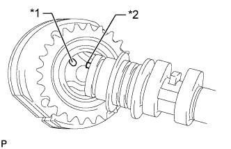
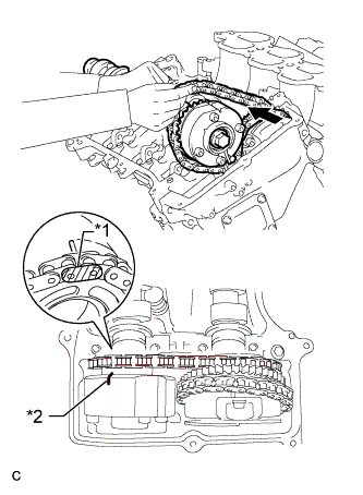
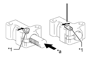
Text in Illustration *1 Pin Hole *2 Straight Pin Put the camshaft timing gear assembly and camshaft together by aligning the pin hole and straight pin.
-
Lightly press and turn the camshaft timing gear assembly against the camshaft, and press harder after the pin enters the hole.
Note
Be sure not to turn the camshaft timing gear assembly in the retard direction.
-
Check that there is no clearance between the camshaft timing gear assembly flange and camshaft.
-
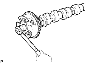
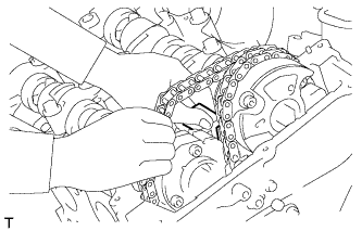
Tighten the flange bolt while holding the camshaft.
- Torque:
- 100 N*m { 1020 kgf*cm, 74 ft.*lbf }
-
Check the lock of the camshaft timing gear assembly.
-
Fix the camshaft in place and confirm that the camshaft timing gear assembly is locked.
Note
Be careful not to damage the camshaft.
-
-
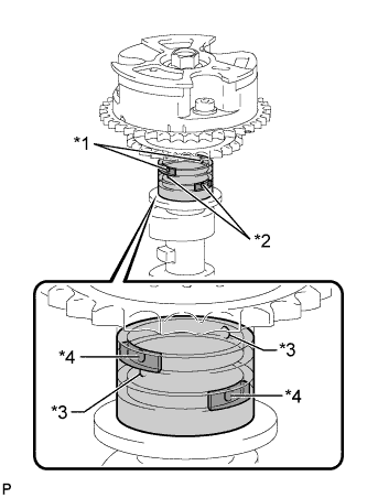
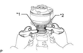
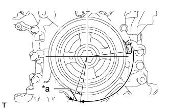
Text in Illustration *1 Advance Side Path *2 Retard Side Path *3 Open *4 Close 
Rubber 
Vinyl Tape Release the lock pin.
-
Cover the 4 oil paths of the cam journal with vinyl tape as shown in the illustration.
Tech Tips
The 2 advance side paths are located in the camshaft groove. Plug one of the paths with a rubber piece.
-
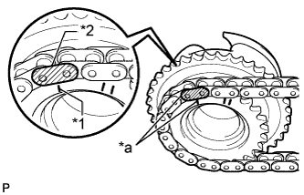
Break through the tape on the advance side path and the retard side path on the opposite side of the hole of the advance side path as shown in the illustration.
-

Text in Illustration *1 Advance Side Path *2 Retard Side Path Apply air at approximately 200 kPa (2.0 kgf/cm2, 28 psi) to the 2 open paths.
CAUTION:
Cover the paths with a piece of cloth when applying pressure to prevent oil from spraying.
-
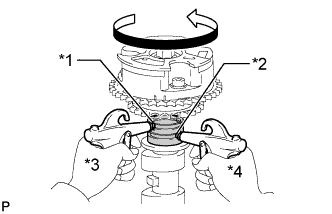
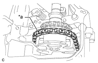
Text in Illustration *1 Advance Side Path *2 Retard Side Path *3 Hold Pressure *4 Decompress Check that the camshaft timing gear assembly rotates in the advance direction when reducing the air pressure applied to the retard side path.
Tech Tips
This operation releases the lock pin at the most retarded position.
-
When the camshaft timing gear assembly reaches the most advanced position, release the air pressure first from the retard side path and next from the advance side path.
Note
Do not release the air pressure from the advance side path first. The gear may abruptly shift in the retard direction and break the lock pin.
-
-
Check for smooth rotation.
-
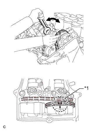
Turn the camshaft timing gear assembly within its movable range (21°) 2 or 3 times, but do not turn it to the most retarded position. Make sure that the gear turns smoothly.
Note
Do not use air pressure to perform the smooth operation check.
-
-
Check the lock in the most retarded position.
-
Confirm that the camshaft timing gear assembly locks at the most retarded position.
-
-
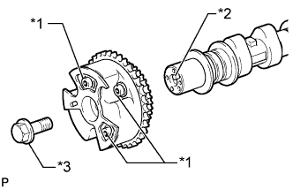
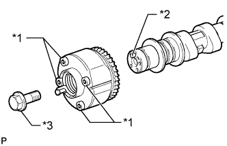
Text in Illustration *1 Do not remove *2 Straight Pin *3 Flange Bolt Remove the flange bolt and camshaft timing gear assembly.
Note
-
Do not remove the other 3 bolts.
-
If planning to reuse the camshaft timing gear, be sure to release the straight pin lock before installing the camshaft timing gear.
-
-
-
INSPECT CAMSHAFT TIMING EXHAUST GEAR ASSEMBLY
-
Fix the camshaft in place.
Note
Be careful not to damage the camshaft.
-
Text in Illustration *1 Pin Hole *2 Straight Pin Put the camshaft timing exhaust gear assembly and camshaft together by aligning the pin hole and straight pin.
-
Lightly press and turn the camshaft timing gear assembly against the camshaft, and press harder after the pin enters the hole.
Note
Be sure not to turn the camshaft timing exhaust gear in the advanced direction.
-
Check that there is no clearance between the gear flange and camshaft.
-
Tighten the flange bolt while holding the camshaft.
- Torque:
- 100 N*m { 1020 kgf*cm, 74 ft.*lbf }
-
Check the camshaft timing exhaust gear lock.
-
Make sure that the camshaft timing exhaust gear assembly locks.
-
-

Text in Illustration *1 Advance Side Path *2 Retard Side Path *3 Open *4 Close Rubber Vinyl Tape Release the lock pin.
-
Cover the 4 oil paths of the cam journal with vinyl tape as shown in the illustration.
Tech Tips
The 2 advance side paths are located in the camshaft groove. Plug one of the paths with a rubber piece.
-
Break through the tape on the advance side path and the retard side path on the opposite side of the hole of the advance side path as shown in the illustration.
-
Text in Illustration *1 Advance Side Path *2 Retard Side Path Apply air at approximately 200 kPa (2.0 kgf/cm2, 28 psi) to the 2 open paths (the advance side path and retard side path).
CAUTION:
Cover the paths with a piece of cloth when applying pressure to prevent oil from spraying.
-
Text in Illustration *1 Advance Side Path *2 Retard Side Path *3 Hold Pressure *4 Decompress Make sure that the camshaft timing exhaust gear assembly rotates in the retard direction when reducing the air pressure applied to the advance side path.
Tech Tips
The lock pin is released and the camshaft timing exhaust gear assembly turns in the retard direction.
-
When the camshaft timing exhaust gear assembly moves to the most retarded position, release the air pressure first from the advance side path, and then release the air pressure from the retard side path.
Note
Be sure to release the air pressure from the advance side path first. If the air pressure of the retard side path is released first, the camshaft timing exhaust gear assembly may abruptly shift in the advance direction and break the lock pin or other parts.
-
-
Check for smooth rotation.
-
Turn the camshaft timing exhaust gear assembly within its movable range (18.5°) 2 or 3 times, but do not turn it to the most advanced position. Make sure that the gear assembly turns smoothly.
Note
When the air pressure is released from the advance side path and then from the retard side path, the gear assembly automatically returns to the most advanced position due to the advance assist spring operation and locks. Gradually release the air pressure from the retard side path before performing the smooth rotation check.
-
-
Check the lock at the most advanced position.
-
Make sure that the camshaft timing exhaust gear assembly locks at the most advanced position.
-
-
Text in Illustration *1 Do not remove *2 Straight Pin *3 Flange Bolt Remove the flange bolt and camshaft timing exhaust gear assembly.
Note
-
Be sure not to remove the other 4 bolts.
-
If planning to reuse the gear, be sure to release the straight pin lock before installing the gear.
-
-
-
INSTALL CAMSHAFT TIMING GEAR ASSEMBLY
-
Fix the camshaft in place.
Note
Be careful not to damage the camshaft.
-
Text in Illustration *1 Pin Hole *2 Straight Pin Put the camshaft timing gear assembly and camshaft together by aligning the pin hole and straight pin.
-
Lightly press and turn the camshaft timing gear assembly against the camshaft, and press harder after the pin enters the hole.
Note
Be sure not to turn the camshaft timing gear assembly in the retard direction.
-
Check that there is no clearance between the camshaft timing gear assembly flange and camshaft.
-
Install the flange bolt while holding the camshaft.
- Torque:
- 100 N*m { 1020 kgf*cm, 74 ft.*lbf }
-
Check the lock of the camshaft timing gear assembly.
-
Fix the camshaft in place and confirm that the camshaft timing gear assembly is locked.
Note
Be careful not to damage the camshaft.
-
-
-
INSTALL CAMSHAFT TIMING EXHAUST GEAR ASSEMBLY
-
Fix the camshaft in place.
Note
Be careful not to damage the camshaft.
-
Text in Illustration *1 Pin Hole *2 Straight Pin Put the camshaft timing exhaust gear assembly and camshaft together by aligning the pin hole and straight pin.
-
Lightly press and turn the camshaft timing gear assembly against the camshaft, and press harder after the pin enters the hole.
Note
Be sure not to turn the camshaft timing exhaust gear in the advanced direction.
-
Check that there is no clearance between the gear flange and camshaft.
-
Install the flange bolt while holding the camshaft.
- Torque:
- 100 N*m { 1020 kgf*cm, 74 ft.*lbf }
-
Check the camshaft timing exhaust gear lock.
-
Make sure that the camshaft timing exhaust gear assembly locks.
-
-
-
INSTALL NO. 3 CAMSHAFT SUB-ASSEMBLY
-
Check that the notch is aligned with the "0" timing mark of the timing chain cover.
-
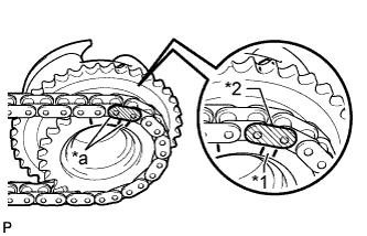
Text in Illustration *1 Timing Mark *2 Mark Plate (yellow) *a Align Align the mark plate (yellow) with the timing mark of the camshaft timing gear as shown in the illustration and install the No. 2 chain to the camshaft timing gear.
-
Clean the camshaft housing LH and camshaft journals and apply engine oil to them.
-
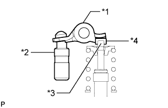
Text in Illustration *1 Valve Rocker Arm *2 Lash Adjuster *3 Valve Stem *4 Valve Stem Cap Make sure that the No. 1 valve rocker arm sub-assembly is installed as shown in the illustration.
-
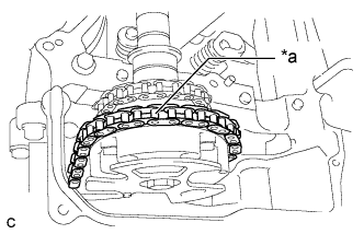
Text in Illustration *a Place on camshaft timing gear Install the chain to the No. 3 camshaft, and then install the camshaft to the camshaft housing LH.
Tech Tips
-
Place the chain on the camshaft timing gear but do not engage the teeth of the sprocket and the chain.
-
Install the camshaft so that the timing mark is facing upward.
-
-
-
INSTALL NO. 4 CAMSHAFT SUB-ASSEMBLY
-
Clean the camshaft housing LH and camshaft journals and apply engine oil to them.
-
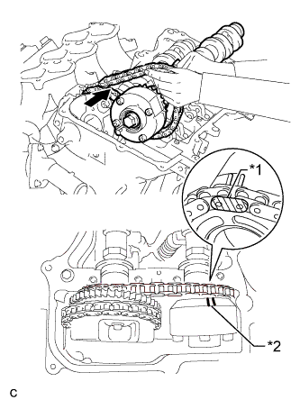
Text in Illustration *1 Mark Plate (yellow) *2 Timing Mark Pass the No. 4 camshaft through the No. 2 chain from the front of the vehicle, align the mark plate (yellow) with the timing mark and install the No. 2 chain to the camshaft timing exhaust gear.
Tech Tips
The mark plate is yellow.
-
While lifting up the No. 4 camshaft, pass the No. 3 chain tensioner assembly through the No. 2 chain and set it in place.
-
Install the No. 4 camshaft to the camshaft housing LH, and then install the No. 3 chain tensioner assembly with the bolt.
- Torque:
- 21 N*m { 214 kgf*cm, 15 ft.*lbf }
-
-
INSTALL CAMSHAFT BEARING CAP (for Bank 2)
-
Clean the camshaft bearing caps and apply engine oil to them.
-
Text in Illustration *1 Valve Rocker Arm *2 Lash Adjuster *3 Valve Stem *4 Valve Stem Cap Make sure that the No. 1 valve rocker arm sub-assembly is installed as shown in the illustration.
-
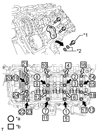
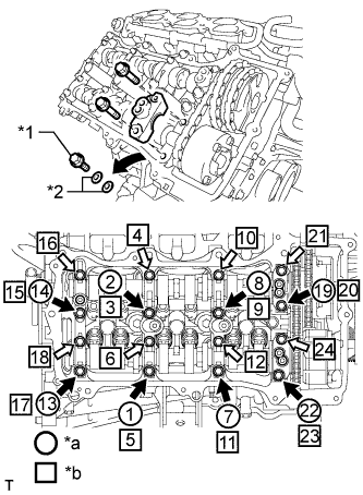
Text in Illustration *1 Bolt *2 Washer *a Installation of Bolts and Washers for Temporary Installation of Camshaft Housing *b Part Installation 
Bolt A 
Bolt B Check the marks and numbers on the camshaft bearing caps, and then remove the replacement bolts and washers in the order shown in the illustration. Immediately after removing the bolts and washers for temporary installation of the camshaft housing in the location for a bearing cap, install the bearing cap with the bolts in the order shown in the illustration.
- Torque:
- for bolt A
- 28 N*m { 286 kgf*cm, 21 ft.*lbf }
- for bolt B
- 16 N*m { 163 kgf*cm, 12 ft.*lbf }
Note
-
Be sure to follow the numerical order when performing this procedure.
-
Do not drop bolts and washers for temporary installation of the camshaft housing into the cylinder head.
-
Check the torque of each bolt again.
-
-
CONNECT CHAIN SUB-ASSEMBLY (for Bank 2)
-
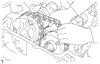
Text in Illustration *1 Paint Mark Align the paint marks on the camshaft timing gear and No. 1 chain and install the No. 1 chain to the camshaft timing gear.
Tech Tips
If the paint marks are not aligned, align them by turning the camshaft slightly.
-
-
INSTALL CAMSHAFT
-
Text in Illustration *a 5° to 10° Turn the crankshaft clockwise until it is in the position shown in the illustration so that the chain can be installed easily.
Note
When turning the crankshaft, engine oil may spray out of the oil holes.
-
Text in Illustration *1 Timing Mark *2 Mark Plate (yellow) *a Align Align the mark plate (yellow) with the timing mark of the camshaft timing gear as shown in the illustration and install the No. 2 chain to the camshaft timing gear.
-
Clean the camshaft housing RH and camshaft journals and apply engine oil to them.
-
Text in Illustration *1 Valve Rocker Arm *2 Lash Adjuster *3 Valve Stem *4 Valve Stem Cap Make sure that the No. 1 valve rocker arm sub-assembly is installed as shown in the illustration.
-
Text in Illustration *a Place on camshaft timing gear Install the chain to the camshaft, and then install the camshaft to the camshaft housing RH.
Tech Tips
-
Place the chain on the camshaft timing gear but do not engage the teeth of the sprocket and the chain.
-
Install the camshaft so that the timing mark is facing upward.
-
-
-
INSTALL NO. 2 CAMSHAFT
-
Clean the camshaft housing RH and camshaft journals and apply engine oil to them.
-
Text in Illustration *1 Mark Plate (yellow) *2 Timing Mark Pass the No. 2 camshaft through the No. 2 chain from the front of the vehicle, align the mark plate (yellow) with the timing mark and install the No. 2 chain to the camshaft timing exhaust gear.
Tech Tips
The mark plate is yellow.
-
While lifting up the No. 2 camshaft, pass the No. 2 chain tensioner assembly through the No. 2 chain and set it in place.
-
Install the No. 2 camshaft to the camshaft housing RH, and then install the No. 2 chain tensioner assembly with the bolt.
- Torque:
- 21 N*m { 214 kgf*cm, 15 ft.*lbf }
-
-
INSTALL CAMSHAFT BEARING CAP (for Bank 1)
-
Clean the camshaft bearing caps and apply engine oil to them.
-
Text in Illustration *1 Valve Rocker Arm *2 Lash Adjuster *3 Valve Stem *4 Valve Stem Cap Make sure that the No. 1 valve rocker arm sub-assembly is installed as shown in the illustration.
-
Text in Illustration *1 Bolt *2 Washer *a Installation of Bolts and Washers for Temporary Installation of Camshaft Housing *b Part Installation Bolt A Bolt B Check the marks and numbers on the camshaft bearing caps, and then remove the replacement bolts and washers in the order shown in the illustration. Immediately after removing the bolts and washers for temporary installation of the camshaft housing in the location for a bearing cap, install the bearing cap with the bolts in the order shown in the illustration.
- Torque:
- for bolt A
- 28 N*m { 286 kgf*cm, 21 ft.*lbf }
- for bolt B
- 16 N*m { 163 kgf*cm, 12 ft.*lbf }
Note
-
Be sure to follow the numerical order when performing this procedure.
-
Do not drop bolts and washers for temporary installation of the camshaft housing into the cylinder head.
-
Check the torque of each bolt again.
-
-
CONNECT CHAIN SUB-ASSEMBLY (for Bank 1)
-
Text in Illustration *1 Paint Mark Align the paint marks on the camshaft timing gear and No. 1 chain and install the No. 1 chain to the camshaft timing gear.
Tech Tips
If the paint marks are not aligned, align them by turning the camshaft slightly.
-
-
INSTALL NO. 1 CHAIN TENSIONER ASSEMBLY
-
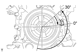
Turn the crankshaft counterclockwise 30° past the "0" timing mark, and then turn it clockwise to align the notch with the "0" timing mark.
-
Turn the crankshaft slightly to eliminate the slack in the chain.
Tech Tips
Make sure there is some slack in the chain around the area where the chain tensioner is installed.
-
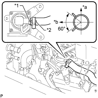
Text in Illustration *1 Stopper Plate *a Push While turning the stopper plate of the tensioner clockwise, push in the plunger of the tensioner as shown in the illustration.
-
While turning the stopper plate of the tensioner counterclockwise, insert a pin with a diameter of 1.27 mm (0.0500 in.) into the holes in the stopper plate and tensioner to fix the stopper plate in place.
-
Install the chain tensioner with the 2 bolts.
- Torque:
- 10 N*m { 102 kgf*cm, 7 ft.*lbf }
-
Remove the pin from the No. 1 chain tensioner.
-
-
INSPECT VALVE TIMING
-
Check the camshaft timing marks.
Note
-
Check each timing mark from a viewpoint directly in line with the center of the camshaft and the timing mark on each camshaft timing gear.
-
If the timing marks are checked from any other viewpoint, the valve timing may appear misaligned.
-
-
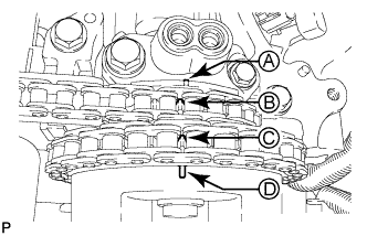
Check that each camshaft timing mark is positioned as shown in the illustration.
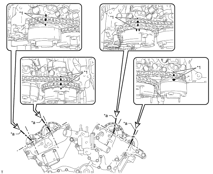
Text in Illustration *1 Timing Mark - - *a Viewpoint - - Tech Tips
for Intake Camshaft:
Be sure to check mark A at the point when marks B, C and D are positioned in line. If the marks are checked from any other viewpoint, they cannot be checked correctly.
-
If the valve timing is misaligned, reinstall the timing chain.
-
Turn the crankshaft 2 revolutions, set the No. 1 cylinder to TDC/compression and check the timing marks again.
-
-
INSTALL TIMING CHAIN COVER PLATE
-
Install a new gasket and the timing chain cover plate with the 4 bolts.
- Torque:
- 9.0 N*m { 92 kgf*cm, 80 in.*lbf }
-
-
POUR ENGINE OIL
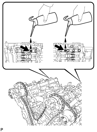
Tech Tips
Before installing the cylinder head cover, pour engine oil into the locations shown in the illustration.
-
INSTALL CYLINDER HEAD COVER SUB-ASSEMBLY
-
Remove any old packing (FIPG material) and be careful not to drop any oil on the contact surfaces of the camshaft housing, timing chain cover and cylinder head cover.
-
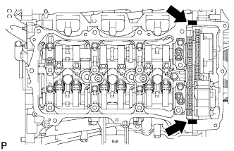
Apply seal packing as shown in the illustration.
Seal packing Toyota Genuine Seal Packing Black, Three Bond 1207B or equivalent Standard seal diameter 2.0 to 3.0 mm (0.0787 to 0.118 in.) Text in Illustration Seal Packing Note
-
Remove any oil from the contact surface.
-
Install the cylinder head cover within 3 minutes and tighten the bolts within 15 minutes after applying seal packing.
-
-
Install 3 new gaskets.
-
Install a new gasket to the cylinder head cover.
-
Install new seal washers to the bolts.
-
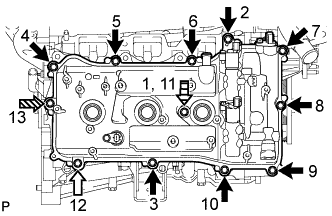
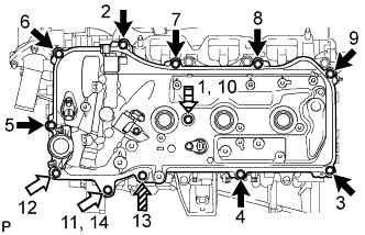
Temporarily install the cylinder head cover with the 12 bolts. Tighten the bolts uniformly in several steps.
- Torque:
- for bolt A and D
- 10 N*m { 102 kgf*cm, 7 ft.*lbf }
- for bolt B and C
- 21 N*m { 214 kgf*cm, 15 ft.*lbf }
Standard Bolt Item Length A 25 mm (0.984 in.) B 35 mm (1.38 in.) C 65 mm (2.56 in.) D 60 mm (2.36 in.) Text in Illustration Bolt A Bolt B 
Bolt C 
Bolt D Note
Do not start the engine for at least 2 hours after installation.
-
-
INSTALL CYLINDER HEAD COVER SUB-ASSEMBLY LH
-
Remove any old packing (FIPG material) and be careful not to drop any oil on the contact surfaces of the camshaft housing, timing chain cover and cylinder head cover.
-
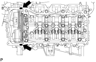
Apply seal packing as shown in the illustration.
Seal packing Toyota Genuine Seal Packing Black, Three Bond 1207B or equivalent Standard seal diameter 2.0 to 3.0 mm (0.0787 to 0.118 in.) Text in Illustration Seal Packing Note
-
Remove any oil from the contact surface.
-
Install the cylinder head cover within 3 minutes and tighten the bolts within 15 minutes after applying seal packing.
-
-
Install 3 new gaskets.
-
Install a new gasket to the cylinder head cover.
-
Install new seal washers to the bolts.
-
Temporarily install the cylinder head cover with the 12 bolts. Tighten the bolts uniformly in several steps.
- Torque:
- for bolt A and D
- 10 N*m { 102 kgf*cm, 7 ft.*lbf }
- for bolt B and C
- 21 N*m { 214 kgf*cm, 15 ft.*lbf }
Standard Bolt Item Length A 25 mm (0.984 in.) B 35 mm (1.38 in.) C 70 mm (2.76 in.) D 60 mm (2.36 in.) Text in Illustration Bolt A Bolt B Bolt C Bolt D Note
Do not start the engine for at least 2 hours after installation.
-
-
CONNECT FUEL PIPE SUB-ASSEMBLY
-
Connect the fuel pipe with the 2 bolts.
- Torque:
- 9.0 N*m { 92 kgf*cm, 80 in.*lbf }
-
-
INSTALL NO. 2 OIL PIPE
-
Make sure that there is no foreign matter on the mesh of the oil control valve filter RH.
Note
Do not touch the mesh when installing the oil control valve filter.
-
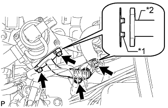
Install a new gasket and temporarily install the oil pipe (on the cylinder head side) with the oil check valve bolt.
-
Install the oil control valve filter RH to the oil pipe union. Install new gaskets and temporarily install the oil pipe (on the cylinder head cover side).
-
Tighten the oil pipe union (on the cylinder head side).
- Torque:
- 65 N*m { 663 kgf*cm, 48 ft.*lbf }
Note
If the link that connects the gaskets is broken, remove the connecting link by using side cutters or a similar tool.
-
Tighten the oil pipe union (on the cylinder head cover side).
- Torque:
- 65 N*m { 663 kgf*cm, 48 ft.*lbf }
-
-
INSTALL NO. 1 OIL PIPE
-
Make sure that there is no foreign matter on the mesh of the oil control valve filter LH.
Note
Do not touch the mesh when installing the oil control valve filter.
-
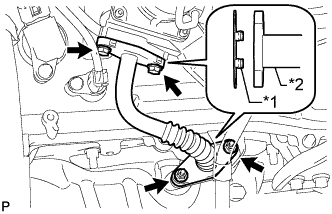
Install a new gasket and temporarily install the oil pipe (on the cylinder head side) with the oil check valve bolt.
-
Install the oil control valve filter LH to the oil pipe union. Install new gaskets and temporarily install the oil pipe (on the cylinder head cover side).
-
Tighten the oil pipe union (on the cylinder head side).
- Torque:
- 65 N*m { 663 kgf*cm, 48 ft.*lbf }
Note
If the link that connects the gaskets is broken, remove the connecting link by using side cutters or a similar tool.
-
Tighten the oil pipe union (on the cylinder head cover side).
- Torque:
- 65 N*m { 663 kgf*cm, 48 ft.*lbf }
-
-
INSTALL WATER BY-PASS PIPE SUB-ASSEMBLY
-
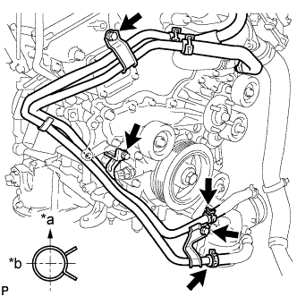
Text in Illustration *a Upward *b Rearward Install the water by-pass pipe with the 3 bolts.
- Torque:
- 10 N*m { 102 kgf*cm, 7 ft.*lbf }
-
Connect the 2 hoses.
Tech Tips
The direction of the hose clamp is indicated in the illustration.
-
-
INSTALL ENGINE OIL LEVEL DIPSTICK GUIDE
-
Text in Illustration *1 New O-Ring Install a new O-ring to the engine oil level dipstick guide.
-
Apply a light coat of engine oil to the O-ring.
-
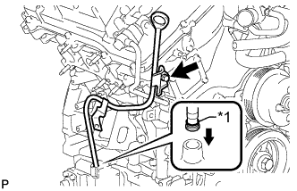
Push the engine oil level dipstick guide end into the guide hole.
-
Install the engine oil level dipstick guide with the bolt.
- Torque:
- 10 N*m { 102 kgf*cm, 7 ft.*lbf }
-
Install the engine oil level dipstick.
-
-
INSTALL GENERATOR ASSEMBLY
-
Install the generator bracket to the generator with the bolt.
- Torque:
- 20 N*m { 204 kgf*cm, 15 ft.*lbf }
-
Install the generator with the 2 bolts.
- Torque:
- 43 N*m { 438 kgf*cm, 32 ft.*lbf }
-
Connect the generator bracket with the bolt.
- Torque:
- 20 N*m { 204 kgf*cm, 15 ft.*lbf }
-
Connect the wire harness clamp bracket with the bolt.
- Torque:
- 8.0 N*m { 82 kgf*cm, 71 in.*lbf }
-
Connect the generator wire to terminal B with the nut.
- Torque:
- 9.8 N*m { 100 kgf*cm, 87 in.*lbf }
-
Close the terminal cap.
-
Connect the generator connector.
-
-
INSTALL NO. 2 EXHAUST MANIFOLD HEAT INSULATOR
-
Install the heat insulator with the 3 bolts.
- Torque:
- 13 N*m { 133 kgf*cm, 10 ft.*lbf }
-
-
INSTALL NO. 2 IDLER PULLEY SUB-ASSEMBLY
-
Install the 2 No. 2 idler pulleys with the 2 bolts.
- Torque:
- 54 N*m { 551 kgf*cm, 40 ft.*lbf }
-
-
CONNECT VANE PUMP ASSEMBLY
-
Connect the vane pump with the 2 bolts.
- Torque:
- 21 N*m { 214 kgf*cm, 15 ft.*lbf }
-
Attach the wire harness clamp.
-
Connect the connector.
-
-
INSTALL IGNITION COIL ASSEMBLY
-
Install the 6 ignition coils with the 6 bolts.
- Torque:
- 10 N*m { 102 kgf*cm, 7 ft.*lbf }
-
Connect the 6 ignition coil connectors.
-
-
INSTALL NO. 2 EMISSION CONTROL VALVE SET (w/ Secondary Air Injection System)
-
Install the No. 2 emission control valve set with the 3 nuts.
- Torque:
- 21 N*m { 214 kgf*cm, 15 ft.*lbf }
-
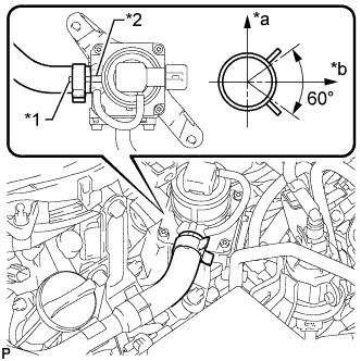
Text in Illustration *1 Paint Mark *2 Rib *a Top *b LH Side Align the paint mark with the rib and connect the No. 1 air hose.
Tech Tips
Make sure the direction of the hose clamp is as shown in the illustration.
-
Connect the No. 2 emission control valve set connector.
-
-
INSTALL NO. 1 EMISSION CONTROL VALVE SET (w/ Secondary Air Injection System)
-
Install the No. 1 emission control valve set with the 3 nuts.
- Torque:
- 21 N*m { 214 kgf*cm, 15 ft.*lbf }
-
Text in Illustration *1 Rib *2 Paint Mark *a RH Side *b Top Align the paint mark with the rib and connect the No. 1 air hose.
Tech Tips
Make sure the direction of the hose clamp is as shown in the illustration.
-
Connect the No. 1 emission control valve set connector.
-
-
INSTALL NO. 2 AIR TUBE (w/ Secondary Air Injection System)
-
Text in Illustration *1 Claw *2 No. 2 Air Tube Install 2 new gaskets.
Note
Make sure the gasket's claws are not caught between the No. 2 emission control valve set and No. 2 air tube.
-
Install the No. 2 air tube with the 2 bolts and 2 nuts.
- Torque:
- 10 N*m { 102 kgf*cm, 7 ft.*lbf }
-
-
INSTALL AIR TUBE (w/ Secondary Air Injection System)
-
Text in Illustration *1 Claw *2 Air Tube Install 2 new gaskets.
Note
Make sure the gasket's claws are not caught between the No. 1 emission control valve set and air tube.
-
Install the air tube with the 2 bolts and 2 nuts.
- Torque:
- 10 N*m { 102 kgf*cm, 7 in.*lbf }
-
-
INSTALL INTAKE AIR SURGE TANK
-
INSTALL FAN SHROUD
-
INSPECT IGNITION TIMING
Note
-
Turn all electrical systems off.
-
Perform the inspection when the cooling fan motor is turned off.
-
Warm up the engine.
-
When using the GTS:
-
Connect the GTS to the DLC3.
-
Enter the following menus: Powertrain / Engine and ECT / Data List / All Data / IGN Advance.
-
Inspect the ignition timing during idling.
Standard ignition timing 8 to 12° BTDC @ idle (transmission in neutral and A/C switch off) -
Check that the ignition timing advances immediately when the engine speed is increased.
-
-
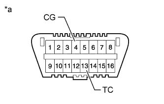
Text in Illustration *a Front view of DLC3 When not using the GTS:
-
Using SST, connect terminals 13 (TC) and 4 (CG) of the DLC3.
- SST
- 09843-18040
Note
Be sure not to improperly connect the terminals. This may damage the engine.
-
Connect the tester probe of a timing light to the wire of the ignition coil connector for the No. 1 cylinder.
Note
-
Use a timing light that detects primary signals.
-
After the inspection, be sure to wrap the wire harness with tape.
-
-
Inspect the ignition timing during idling.
Standard ignition timing 8 to 12° BTDC @ idle (transmission in neutral and A/C switch off) -
Remove SST from the DLC3.
-
Inspect the ignition timing during idling.
Standard ignition timing 7 to 24° BTDC @ idle (transmission in neutral and A/C switch off) -
Disconnect the timing light from the engine.
-
-