CAMSHAFT REMOVAL

-
REMOVE FAN SHROUD
-
REMOVE INTAKE AIR SURGE TANK
-
REMOVE AIR TUBE (w/ Secondary Air Injection System)
-
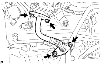
Remove the 2 bolts, 2 nuts and air tube.
-
Remove the 2 gaskets.
Note
Be careful not to damage the installation surface of the gaskets.
-
-
REMOVE NO. 2 AIR TUBE (w/ Secondary Air Injection System)
-
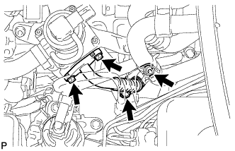
Remove the 2 bolts, 2 nuts and No. 2 air tube.
-
Remove the 2 gaskets.
Note
Be careful not to damage the installation surface of the gaskets.
-
-
REMOVE NO. 1 EMISSION CONTROL VALVE SET (w/ Secondary Air Injection System)
-
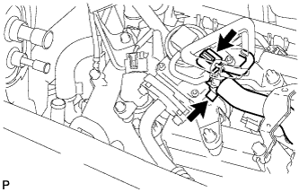
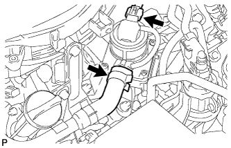
Disconnect the No. 1 emission control valve set connector.
-
Disconnect the No. 1 air hose from the No. 1 emission control valve set.
-
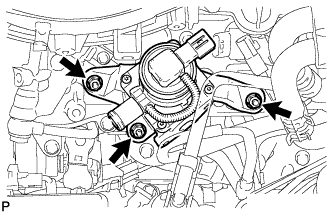
Remove the 3 nuts and No. 1 emission control valve set.
-
-
REMOVE NO. 2 EMISSION CONTROL VALVE SET (w/ Secondary Air Injection System)
-
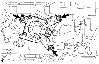
Disconnect the No. 2 emission control valve set connector.
-
Disconnect the No. 3 air hose.
-
Remove the 3 nuts and No. 2 emission control valve set.
-
-
REMOVE IGNITION COIL ASSEMBLY
-
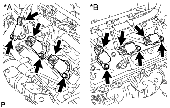
Text in Illustration *A Bank 1 *B Bank 2 Disconnect the 6 ignition coil connectors.
-
Remove the 6 bolts and 6 ignition coils.
-
-
DISCONNECT VANE PUMP ASSEMBLY
-
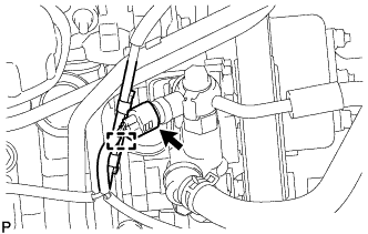
Disconnect the connector.
-
Detach the wire harness clamp.
-
Remove the 2 bolts and disconnect the vane pump.
-
-
REMOVE NO. 2 IDLER PULLEY SUB-ASSEMBLY
-
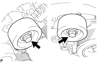
Remove the 2 bolts and 2 No. 2 idler pulleys.
-
-
REMOVE NO. 2 EXHAUST MANIFOLD HEAT INSULATOR
-
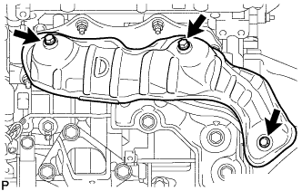
Remove the 3 bolts and heat insulator.
-
-
REMOVE GENERATOR ASSEMBLY
-
Disconnect the generator connector.
-
Open the terminal cap.
-
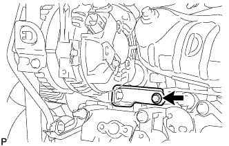
Remove the nut and disconnect the generator wire from terminal B.
-
Remove the bolt and disconnect the wire harness clamp bracket.
-
Remove the bolt and disconnect the generator bracket.
-
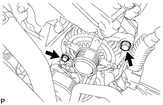
Remove the 2 bolts and generator.
-
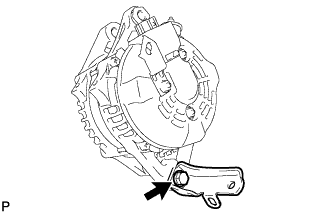
Remove the bolt and generator bracket.
-
-
REMOVE ENGINE OIL LEVEL DIPSTICK GUIDE
-
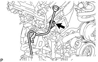
Remove the engine oil level dipstick.
-
Remove the bolt and engine oil level dipstick guide.
-
Remove the O-ring from the engine oil level dipstick guide.
-
-
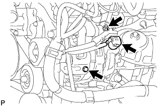
REMOVE WATER BY-PASS PIPE SUB-ASSEMBLY
-
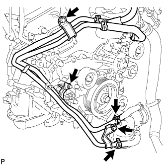
Disconnect the 2 hoses.
-
Remove the 3 bolts and water by-pass pipe.
-
-
REMOVE NO. 1 OIL PIPE
-
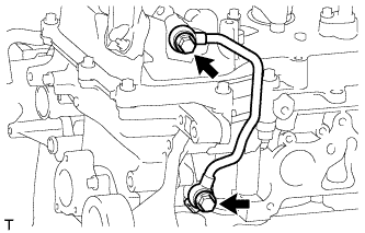
Remove the 2 oil pipe unions, oil control valve filter LH, 3 gaskets and No. 1 oil pipe.
Note
Do not touch the mesh when removing the oil control valve filter.
-
-
REMOVE NO. 2 OIL PIPE
-
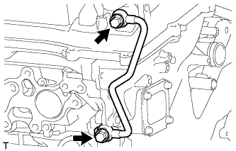
Remove the 2 oil pipe unions, oil control valve filter RH, 3 gaskets and No. 2 oil pipe.
Note
Do not touch the mesh when removing the oil control valve filter.
-
-
DISCONNECT FUEL PIPE SUB-ASSEMBLY
-
Remove the 2 bolts and disconnect the fuel pipe.
-
-
REMOVE CYLINDER HEAD COVER SUB-ASSEMBLY LH
-
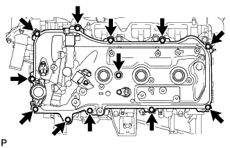
Remove the 12 bolts, seal washer, cylinder head cover and gasket.
Tech Tips
Make sure the removed parts are returned to the same places they were removed from.
-
Remove the 3 gaskets.
-
-
REMOVE CYLINDER HEAD COVER SUB-ASSEMBLY
-
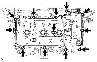
Remove the 12 bolts, seal washer, cylinder head cover and gasket.
Tech Tips
Make sure the removed parts are returned to the same places they were removed from.
-
Remove the 3 gaskets.
-
-
REMOVE TIMING CHAIN COVER PLATE
-
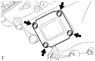
Remove the 4 bolts, timing chain cover plate and gasket.
-
-
SET NO. 1 CYLINDER TO TDC/COMPRESSION
-
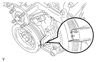
Turn the crankshaft pulley and align the notch with the "0" timing mark of the timing chain cover.
-
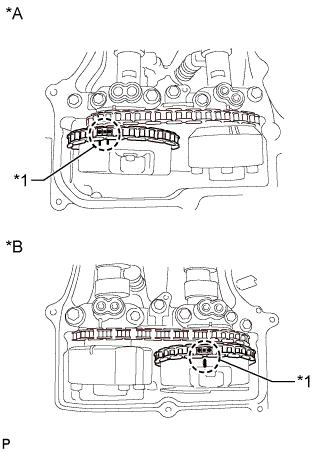
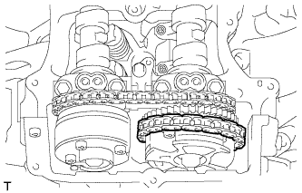
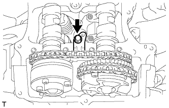
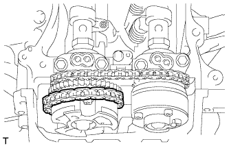
Text in Illustration *A for Bank 2 *B for Bank 1 *1 Paint Mark Check that the timing marks of the camshaft timing gears are aligned with the timing marks of the bearing caps as shown in the illustration.
Tech Tips
If the marks are not aligned, turn the crankshaft again to align the marks.
-
Place paint marks on the timing marks and sprockets of each camshaft timing gear and on the links of the No. 1 chain.
Tech Tips
Be sure to place the paint marks on 2 links of the chain and on the sprockets of the camshaft timing gears at the locations of the timing marks of the camshaft timing gears.
-
-
REMOVE NO. 1 CHAIN TENSIONER ASSEMBLY
-
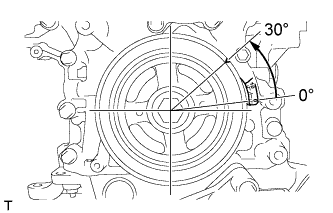
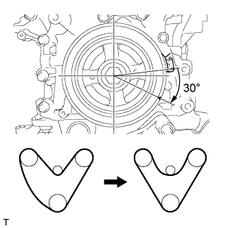
Turn the crankshaft approximately 30° counterclockwise so that there is some slack in the chain.
Tech Tips
This prevents the valves and pistons from interfering with each other.
-
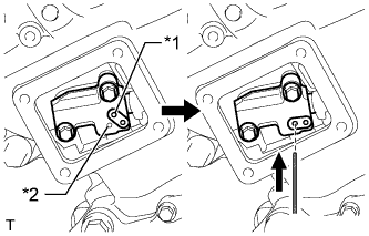
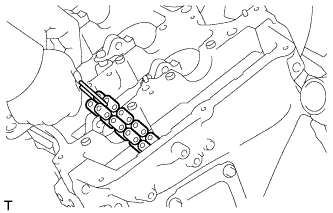
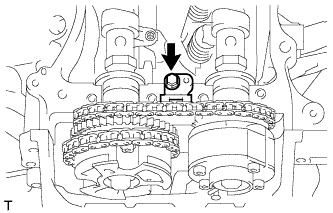
Text in Illustration *1 Lever Hole *2 Tensioner Hole Align the hole in the lever of the tensioner with the hole in the tensioner body as shown in the illustration, and then insert a pin with a diameter of 1.27 mm (0.0500 in.) into the hole.
-
Turn the crankshaft clockwise and align the notch with the "0" timing mark of the timing chain cover.
-
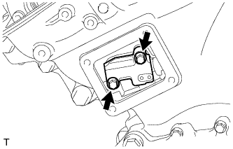
Remove the 2 bolts and chain tensioner.
Note
Do not drop the No. 1 chain tensioner assembly or bolts into the timing chain cover.
-
-
DISCONNECT CHAIN SUB-ASSEMBLY (for Bank 1)
-
Turn the crankshaft clockwise until it is in the position shown in the illustration so that there is some slack in the chain between the banks.
CAUTION:
As the camshafts turn suddenly, do not touch the camshafts or camshaft timing gears.
Note
When turning the crankshaft, engine oil may spray out of the oil holes.
-
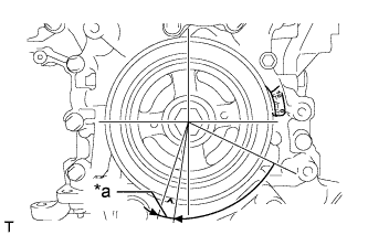
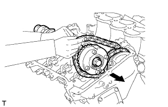
Text in Illustration *a 5° to 10° Turn the crankshaft clockwise until it is in the position shown in the illustration so that the chain can be removed easily.
Note
When turning the crankshaft, engine oil may spray out of the oil holes.
-
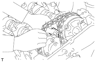
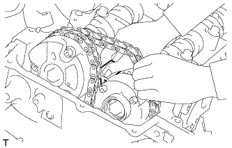
Remove the chain from the sprocket of the camshaft timing gear and set it on the gear.
CAUTION:
As the camshaft may turn suddenly and pinch your fingers when the chain is removed, pinch the chain and lift it upward to remove it from the sprocket.
-
-
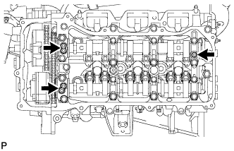
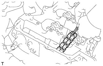
REMOVE CAMSHAFT BEARING CAP (for Bank 1)
-
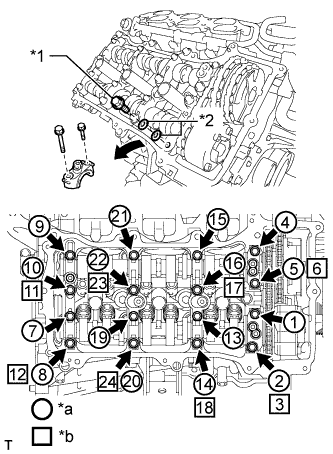
Text in Illustration *1 Bolt *2 Washer *a Part Removal *b Installation of Bolts and Washers for Temporary Installation of Camshaft Housing Remove the bolts and bearing caps in the order shown in the illustration. Immediately after removing a bearing cap, install bolts and washers for temporary installation of the camshaft housing in the order shown in the illustration.
- Torque:
- 10 N*m { 102 kgf*cm, 7 ft.*lbf }
Note
-
Do not install the bearing caps when installing bolts and washers for temporary installation of the camshaft housing.
-
Be sure to follow the numerical order when performing this procedure.
-
Do not allow bolts and washers for temporary installation of the camshaft housing to contact the camshaft.
-
Do not drop bolts and washers for temporary installation of the camshaft housing into the cylinder head.
Tech Tips
-
Arrange the removed parts so that they can be reinstalled in their original locations.
-
Part number of bolt for temporary installation of camshaft housing: 91551-G0845 (quantity: 8)
-
Part number of washer for temporary installation of camshaft housing: 90201-12028 (quantity: 16)
-
-
REMOVE NO. 2 CAMSHAFT
-
Remove the bolt of the No. 2 chain tensioner assembly.
-
Remove the No. 2 chain tensioner assembly while lifting up the No. 2 camshaft.
-
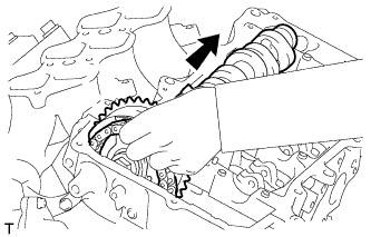
While lifting up the No. 2 camshaft, pass it through the No. 2 chain and pull it out towards the front of the vehicle to remove it.
-
-
REMOVE CAMSHAFT
-
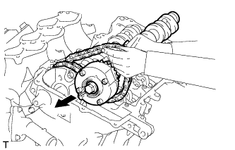
Lift up the rear of the camshaft so that it is at an angle.
-
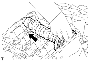
Remove the chain from the camshaft timing gear and pull out the camshaft and No. 2 chain towards the rear of the vehicle to remove them.
Note
Do not drop the chain into the gap between the engine and cover.
-
Suspend the chain with a string or equivalent.
-
-
DISCONNECT CHAIN SUB-ASSEMBLY (for Bank 2)
-
Turn the crankshaft counterclockwise and align the notch with the "0" timing mark of the timing chain cover.
-
Remove the chain from the sprocket of the camshaft timing gear and set it on the gear.
CAUTION:
As the camshaft may turn suddenly and pinch your fingers when the chain is removed, pinch the chain and lift it upward to remove it from the sprocket.
-
-
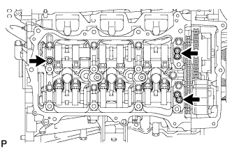
REMOVE CAMSHAFT BEARING CAP (for Bank 2)
-
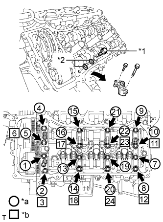
Text in Illustration *1 Bolt *2 Washer *a Part Removal *b Installation of Bolts and Washers for Temporary Installation of Camshaft Housing Remove the bolts and bearing caps in the order shown in the illustration. Immediately after removing a bearing cap, install bolts and washers for temporary installation of the camshaft housing in the order shown in the illustration.
- Torque:
- 10 N*m { 102 kgf*cm, 7 ft.*lbf }
Note
-
Do not install the bearing caps when installing bolts and washers for temporary installation of the camshaft housing.
-
Be sure to follow the numerical order when performing this procedure.
-
Do not allow bolts and washers for temporary installation of the camshaft housing to contact the camshaft.
-
Do not drop bolts and washers for temporary installation of the camshaft housing into the cylinder head.
Tech Tips
-
Arrange the removed parts so that they can be reinstalled in their original locations.
-
Part number of bolt for temporary installation of camshaft housing: 91551-G0845 (quantity: 8)
-
Part number of washer for temporary installation of camshaft housing: 90201-12028 (quantity: 16)
-
-
REMOVE NO. 4 CAMSHAFT SUB-ASSEMBLY
-
Remove the bolt of the No. 3 chain tensioner assembly.
-
Remove the No. 3 chain tensioner assembly while lifting up the No. 4 camshaft.
-
While lifting up the No. 4 camshaft, pass it through the No. 2 chain and pull it out towards the front of the vehicle to remove it.
-
-
REMOVE NO. 3 CAMSHAFT SUB-ASSEMBLY
-
Lift up the rear of the camshaft so that it is at an angle.
-
Remove the chain from the camshaft timing gear and pull out the No. 3 camshaft and No. 2 chain towards the rear of the vehicle to remove them.
Note
Do not drop the chain into the gap between the engine and cover.
-
Suspend the chain with a string or equivalent.
-
-
REMOVE CAMSHAFT TIMING GEAR ASSEMBLY
-
Fix the camshaft in place.
Note
Be careful not to damage the camshaft.
-
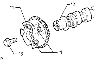
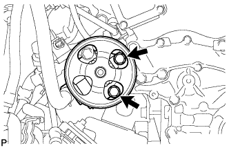
Text in Illustration *1 Do not remove *2 Straight Pin *3 Flange Bolt Remove the flange bolt and camshaft timing gear assembly.
Note
-
Do not remove the other 3 bolts.
-
If planning to reuse the camshaft timing gear, be sure to release the straight pin lock before installing the camshaft timing gear.
-
-
-
REMOVE CAMSHAFT TIMING EXHAUST GEAR ASSEMBLY
-
Fix the camshaft in place.
Note
Be careful not to damage the camshaft.
-
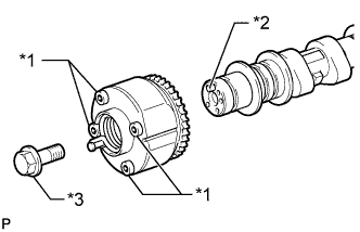
Text in Illustration *1 Do not remove *2 Straight Pin *3 Flange Bolt Remove the flange bolt and camshaft timing exhaust gear assembly.
Note
-
Be sure not to remove the other 4 bolts.
-
If planning to reuse the gear, be sure to release the straight pin lock before installing the gear.
-
-