ECD SYSTEM (w/o DPF), Diagnostic DTC:P1258, P1259, P1260, P1262, P1263, P2563, P2564, P2565, P2588, P2589

| DTC Code | DTC Name |
|---|---|
| P1258 | VNT Position Sensor Range/Performance Bank 2 Sensor 1 |
| P1259 | VNT Position Sensor Low Bank 2 Sensor 1 |
| P1260 | VNT Position Sensor High Bank 2 Sensor 1 |
| P1262 | VNT Position Sensor Low Bank 2 Sensor 2 |
| P1263 | VNT Position Sensor High Bank 2 Sensor 2 |
| P2563 | Turbocharger/Supercharger Boost Control Position Sensor "A" Circuit Range/Performance |
| P2564 | Turbocharger/Supercharger Boost Control Position Sensor "A" Circuit Low |
| P2565 | Turbocharger/Supercharger Boost Control Position Sensor "A" Circuit High |
| P2588 | Turbocharger/Supercharger Boost Control Position Sensor "B" Circuit Low |
| P2589 | Turbocharger/Supercharger Boost Control Position Sensor "B" Circuit High |
DESCRIPTION
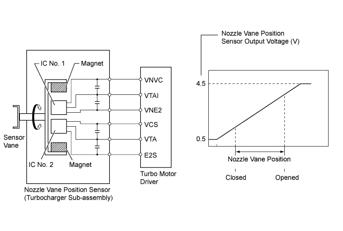
The variable nozzle vane type turbocharger consists primarily of a compressor wheel, turbine wheel, nozzle vane, unison ring, DC motor and nozzle vane position sensor.
The nozzle vane position sensor consists of a Hall IC and a magnetic yoke that rotates in unison with the movement of the linkage that actuates the nozzle vane. The nozzle vane position sensor converts the changes in the magnetic flux that are caused by the rotation of the DC motor (hence, the rotation of the magnetic yoke) into electric signals, and outputs them to the turbo motor driver. The turbo motor driver determines the actual nozzle vane position from the electric signals in order to calculate the target nozzle vane position.
| DTC Detection Drive Pattern | DTC Detection Condition | Trouble Area |
|---|---|---|
| Ignition switch ON for 1 second | The difference between VTI2 and VTA2 voltage is 0.8 V or more for 0.5 seconds (1 trip detection logic). | Nozzle vane position sensor (turbocharger sub-assembly) |
| DTC Detection Drive Pattern | DTC Detection Condition | Trouble Area |
|---|---|---|
| Ignition switch ON for 1 second | VTI2 voltage is 0.5 V or less for 0.5 seconds (1 trip detection logic). |
|
| DTC Detection Drive Pattern | DTC Detection Condition | Trouble Area |
|---|---|---|
| Ignition switch ON for 1 second | VTI2 voltage is 4.5 V or more for 0.5 seconds (1 trip detection logic). |
|
| DTC Detection Drive Pattern | DTC Detection Condition | Trouble Area |
|---|---|---|
| Ignition switch ON for 1 second | VTA2 voltage is 0.5 V or less for 0.5 seconds (1 trip detection logic). |
|
| DTC Detection Drive Pattern | DTC Detection Condition | Trouble Area |
|---|---|---|
| Ignition switch ON for 1 second | VTA2 voltage is 4.5 V or more for 0.5 seconds (1 trip detection logic). |
|
| DTC Detection Drive Pattern | DTC Detection Condition | Trouble Area |
|---|---|---|
| Ignition switch ON for 1 second | The difference between VTA1 and VTA voltage is 0.8 V or more for 0.5 seconds (1 trip detection logic). | Nozzle vane position sensor (turbocharger sub-assembly) |
| DTC Detection Drive Pattern | DTC Detection Condition | Trouble Area |
|---|---|---|
| Ignition switch ON for 1 second | VTA1 voltage is 0.5 V or less for 0.5 seconds (1 trip detection logic). |
|
| DTC Detection Drive Pattern | DTC Detection Condition | Trouble Area |
|---|---|---|
| Ignition switch ON for 1 second | VTA1 voltage is 4.5 V or more for 0.5 seconds (1 trip detection logic). |
|
| DTC Detection Drive Pattern | DTC Detection Condition | Trouble Area |
|---|---|---|
| Ignition switch ON for 1 second | VTA voltage is 0.5 V or less for 0.5 seconds (1 trip detection logic). |
|
| DTC Detection Drive Pattern | DTC Detection Condition | Trouble Area |
|---|---|---|
| Ignition switch ON for 1 second | VTA voltage is 4.5 V or more for 0.5 seconds (1 trip detection logic). |
|
Tech Tips
If DTC P1258, P1259, P1260, P1262, P1263, P2563, P2564, P2565, P2588 and/or P2589 is stored, the following symptoms may appear:
Stuck open malfunction:
-
- Lack of power
-
- Vehicle surge or hesitation under light or medium load
-
- White smoke
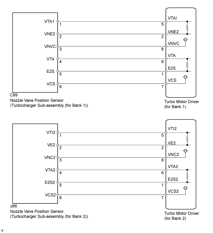
WIRING DIAGRAM
INSPECTION PROCEDURE
Tech Tips
Read freeze frame data using the intelligent tester. Freeze frame data records the engine condition when malfunctions are detected. When troubleshooting, freeze frame data can help determine if the vehicle was moving or stationary, if the engine was warmed up or not, and other data from the time the malfunction occurred.
PROCEDURE
-
INSPECT TURBO MOTOR DRIVER (for Bank 1 and Bank 2)
-
Remove the rear fender splash shield sub-assembly RH.
-
Remove the front fender liner LH.
-
Connect the intelligent tester to the DLC3.
-
Turn the ignition switch to ON and turn the tester on.
-
Enter the following menus: Powertrain / Engine / DTC.
-
Read the DTCs.
Tech Tips
Record the output DTCs.
-
Clear the DTCs Click here.
-
Turn the ignition switch off.
-
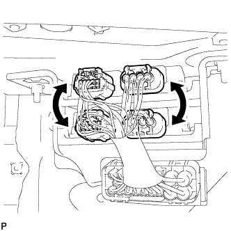
Interchange the connectors for the turbo motor driver of bank 1 and bank 2.
-
Turn the ignition switch to ON for 1 second.
-
Enter the following menus: Powertrain / Engine / DTC.
-
Read the DTCs.
Result Display (DTC Output) Proceed to DTCs change B DTCs do not change A
B 
REPLACE TURBO MOTOR DRIVER (for Bank 1 or Bank 2) Click here
A 
-
-
CHECK HARNESS AND CONNECTOR (TURBO MOTOR DRIVER - NOZZLE VANE POSITION SENSOR)
-
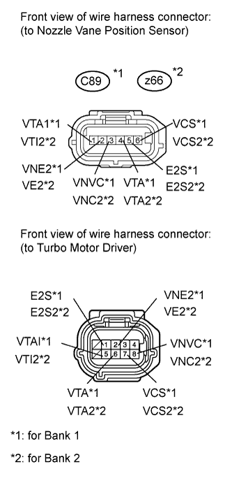
Disconnect the nozzle vane position sensor connector.
-
Disconnect the turbo motor driver connector.
-
Measure the resistance according to the value(s) in the table below.
Standard Resistance (Check for Open) for Bank 1 Tester Connection Condition Specified Condition Turbo motor driver connector-5 (VTAI) - C89-1 (VTA1) Always Below 1 Ω Turbo motor driver connector-2 (VNE2) - C89-2 (VNE2) Always Below 1 Ω Turbo motor driver connector-8 (VNVC) - C89-3 (VNVC) Always Below 1 Ω Turbo motor driver connector-6 (VTA) - C89-4 (VTA) Always Below 1 Ω Turbo motor driver connector-1 (E2S) - C89-5 (E2S) Always Below 1 Ω Turbo motor driver connector-7 (VCS) - C89-6 (VCS) Always Below 1 Ω for Bank 2 Tester Connection Condition Specified Condition Turbo motor driver connector-5 (VTI2) - z66-1 (VTI2) Always Below 1 Ω Turbo motor driver connector-2 (VE2) - z66-2 (VE2) Always Below 1 Ω Turbo motor driver connector-8 (VNC2) - z66-3 (VNC2) Always Below 1 Ω Turbo motor driver connector-6 (VTA2) - z66-4 (VTA2) Always Below 1 Ω Turbo motor driver connector-1 (E2S2) - z66-5 (E2S2) Always Below 1 Ω Turbo motor driver connector-7 (VCS2) - z66-6 (VCS2) Always Below 1 Ω Standard Resistance (Check for Short) for Bank 1 Tester Connection Condition Specified Condition Turbo motor driver connector-5 (VTAI) or C89-1 (VTA1) - Body ground Always 10 kΩ or higher Turbo motor driver connector-2 (VNE2) or C89-2 (VNE2) - Body ground Always 10 kΩ or higher Turbo motor driver connector-8 (VNVC) or C89-3 (VNVC) - Body ground Always 10 kΩ or higher Turbo motor driver connector-6 (VTA) or C89-4 (VTA) - Body ground Always 10 kΩ or higher Turbo motor driver connector-1 (E2S) or C89-5 (E2S) - Body ground Always 10 kΩ or higher Turbo motor driver connector-7 (VCS) or C89-6 (VCS) - Body ground Always 10 kΩ or higher for Bank 2 Tester Connection Condition Specified Condition Turbo motor driver connector-5 (VTI2) or z66-1 (VTI2) - Body ground Always 10 kΩ or higher Turbo motor driver connector-2 (VE2) or z66-2 (VE2) - Body ground Always 10 kΩ or higher Turbo motor driver connector-8 (VNC2) or z66-3 (VNC2) - Body ground Always 10 kΩ or higher Turbo motor driver connector-6 (VTA2) or z66-4 (VTA2) - Body ground Always 10 kΩ or higher Turbo motor driver connector-1 (E2S2) or z66-5 (E2S2) - Body ground Always 10 kΩ or higher Turbo motor driver connector-7 (VCS2) or z66-6 (VCS2) - Body ground Always 10 kΩ or higher
NG
REPAIR OR REPLACE HARNESS OR CONNECTOR Click here
OK
-
-
REPLACE TURBOCHARGER SUB-ASSEMBLY (for Bank 1 or Bank 2) (NOZZLE VANE POSITION SENSOR)
-
Replace the turbocharger sub-assembly (for Bank 1 or Bank 2) Click here.
NEXT
CONFIRM WHETHER MALFUNCTION HAS BEEN SUCCESSFULLY REPAIRED Click here
-
-
REPLACE TURBO MOTOR DRIVER (for Bank 1 or Bank 2)
-
Replace the turbo motor driver (for Bank 1 or Bank 2) Click here.
NEXT
CONFIRM WHETHER MALFUNCTION HAS BEEN SUCCESSFULLY REPAIRED Click here
-
-
REPAIR OR REPLACE HARNESS OR CONNECTOR
NEXT
-
CONFIRM WHETHER MALFUNCTION HAS BEEN SUCCESSFULLY REPAIRED
-
Connect the intelligent tester to the DLC3.
-
Clear the DTCs Click here.
-
Turn the ignition switch off.
-
Turn the ignition switch off and leave the vehicle for 15 seconds.
-
Turn the ignition switch to ON for 1 second.
-
Confirm that the DTC is not output again.
Tech Tips
Perform the following procedure using the tester to determine whether or not the DTC judgment has been carried out
-
Enter the following menus: Powertrain / Engine / Utility / All Readiness.
-
Input DTC P1258, P1259, P1260, P1262, P1263, P2563, P2564, P2565, P2588 and/or P2589.
-
Check that STATUS is NORMAL. If STATUS is INCOMPLETE or UNKNOWN, idle the engine.
-
NEXT 
END
-