ECD SYSTEM (w/o DPF), Diagnostic DTC:P0560

| DTC Code | DTC Name |
|---|---|
| P0560 | System Voltage |
DESCRIPTION
The battery supplies electricity to the ECM even when the ignition switch is off. This power allows the ECM to store data such as DTC history, freeze frame data and fuel trim values. If the battery voltage falls below a minimum level, the ECM memory is cleared and the ECM determines that there is a malfunction in the power supply circuit. When the engine is next started, the ECM illuminates the MIL and stores the DTC.
| DTC Detection Drive Pattern | DTC Detection Condition | Trouble Area |
|---|---|---|
| Ignition switch ON for 3 seconds | The voltage at terminal BATT drops excessively for 3 seconds and part of the stored values in the ECU are initialized (1 trip detection logic). |
|
| DTC No. | Data List |
|---|---|
| P0560 | Battery Voltage |
Tech Tips
If DTC P0560 is stored, the ECM does not store other DTCs or the data stored in the ECM is partly erased.
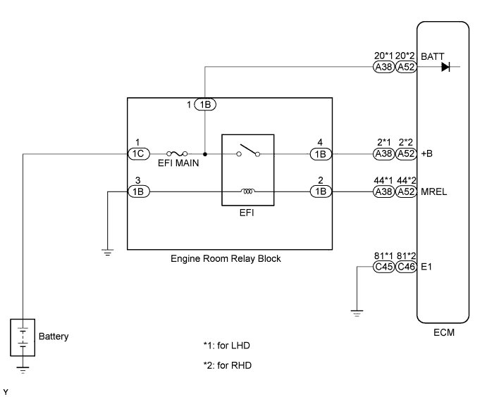
WIRING DIAGRAM
INSPECTION PROCEDURE
Note
After replacing the ECM, the new ECM needs registration Click here and initialization Click here.
Tech Tips
-
Read freeze frame data using the intelligent tester. Freeze frame data records the engine condition when malfunctions are detected. When troubleshooting, freeze frame data can help determine if the vehicle was moving or stationary, if the engine was warmed up or not, and other data from the time the malfunction occurred.
-
When the ignition switch is ON, even though +B voltage is present, when the voltage at terminal BATT (power supply for maintaining memorized values in the ECM) drops excessively, a DTC is stored.
PROCEDURE
-
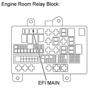
INSPECT FUSE (EFI MAIN)
-
Remove the EFI MAIN fuse from the engine room relay block.
-
Measure the resistance according to the value(s) in the table below.
Standard Resistance Tester Connection Condition Specified Condition EFI MAIN Fuse Always Below 1 Ω
NG 
CHECK FOR SHORTS IN ALL HARNESSES AND CONNECTORS CONNECTED TO FUSE AND REPLACE FUSE Click here
OK 
-
-
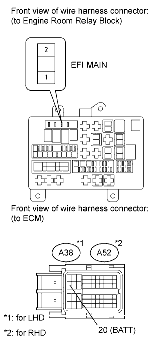
CHECK HARNESS AND CONNECTOR (ENGINE ROOM RELAY BLOCK - ECM, BATTERY)
-
Check the harness and the connector between the EFI MAIN fuse and ECM.
-
Remove the EFI MAIN fuse from the engine room relay block.
-
Disconnect the ECM connector.
-
Measure the resistance according to the value(s) in the table below.
Standard Resistance (Check for Open) for LHD Tester Connection Condition Specified Condition EFI MAIN fuse (2) - A38-20 (BATT) Always Below 1 Ω for RHD Tester Connection Condition Specified Condition EFI MAIN fuse (2) - A52-20 (BATT) Always Below 1 Ω Standard Resistance (Check for Short) for LHD Tester Connection Condition Specified Condition EFI MAIN fuse (2) or A38-20 (BATT) - Body ground Always 10 kΩ or higher for RHD Tester Connection Condition Specified Condition EFI MAIN fuse (2) or A52-20 (BATT) - Body ground Always 10 kΩ or higher
-
-
Check the harness and the connector between the EFI MAIN fuse and battery.
-
Remove the EFI MAIN fuse from the engine room relay block.
-
Disconnect the cable from the positive (+) battery terminal.
-
Measure the resistance according to the value(s) in the table below.
Standard Resistance (Check for Open) Tester Connection Condition Specified Condition Battery positive terminal - EFI MAIN fuse (1) Always Below 1 Ω Standard Resistance (Check for Short) Tester Connection Condition Specified Condition Battery positive terminal or EFI MAIN fuse (1) - Body ground Always 10 kΩ or higher
-
NG
REPAIR OR REPLACE HARNESS OR CONNECTOR Click here
OK
-
-
INSPECT BATTERY
-
Check that the battery is not depleted.
OK Battery is not depleted.
NG
REPLACE BATTERY Click here
OK
-
-
CHECK BATTERY TERMINAL
-
Check that the battery terminals are not loose or corroded.
OK Battery terminals are not loose or corroded.
NG
REPAIR OR REPLACE BATTERY TERMINAL Click here
OK
-
-
CHECK WHETHER DTC OUTPUT RECURS
-
Connect the intelligent tester to the DLC3.
-
Turn the ignition switch to ON and turn the tester on.
-
Clear the DTCs Click here.
-
Turn the ignition switch off.
-
Turn the ignition switch to ON for 3 seconds.
-
Enter the following menus: Powertrain / Engine / DTC.
-
Read the DTCs.
Result Result Proceed to P0560 is output A No DTC is output B
B 
END
A
-
-
REPLACE ECM
-
Replace the ECM Click here.
NEXT
CONFIRM WHETHER MALFUNCTION HAS BEEN SUCCESSFULLY REPAIRED Click here
-
-
CHECK FOR SHORTS IN ALL HARNESSES AND CONNECTORS CONNECTED TO FUSE AND REPLACE FUSE
NEXT
CONFIRM WHETHER MALFUNCTION HAS BEEN SUCCESSFULLY REPAIRED Click here
-
REPAIR OR REPLACE HARNESS OR CONNECTOR
NEXT
CONFIRM WHETHER MALFUNCTION HAS BEEN SUCCESSFULLY REPAIRED Click here
-
REPLACE BATTERY
NEXT
CONFIRM WHETHER MALFUNCTION HAS BEEN SUCCESSFULLY REPAIRED Click here
-
REPAIR OR REPLACE BATTERY TERMINAL
NEXT
-
CONFIRM WHETHER MALFUNCTION HAS BEEN SUCCESSFULLY REPAIRED
-
Connect the intelligent tester to the DLC3.
-
Clear the DTCs Click here.
-
Turn the ignition switch off.
-
Turn the ignition switch to ON for 3 seconds.
-
Enter the following menus: Powertrain / Engine / DTC.
-
Confirm that the DTC is not output again.
NEXT 
END
-