ECD SYSTEM (w/o DPF), Diagnostic DTC:P0488, P213B

| DTC Code | DTC Name |
|---|---|
| P0488 | Exhaust Gas Recirculation Throttle Position Control Range / Performance |
| P213B | Exhaust Gas Recirculation Throttle Position Control (Range / Performance) |
DESCRIPTION
The ECM opens and closes the throttle valve using a rotary solenoid type actuator. Due to the opening and closing of the valve, the exhaust gas recirculation volume can be properly controlled. Also, engine vibration and noise will be reduced by closing the valve when the engine is stopped.
| DTC Detection Drive Pattern | DTC Detection Condition | Trouble Area |
|---|---|---|
| Over a period of 10 seconds or more, slowly raise engine speed to 3000 rpm and lower it | The throttle motor activation duty is less than 10% or 90% or more for 30 seconds (1 trip detection logic). Tech Tips The throttle valve commanded duty can be read using the tester as the Data List item Throttle Motor Duty. |
|
| DTC No. | Data List |
|---|---|
| P0488 |
|
| P213B |
| Condition | Throttle Valve Position |
|---|---|
| Moment when accelerator pedal is depressed further or released at 3000 rpm | Throttle valve opening angle varies smoothly |
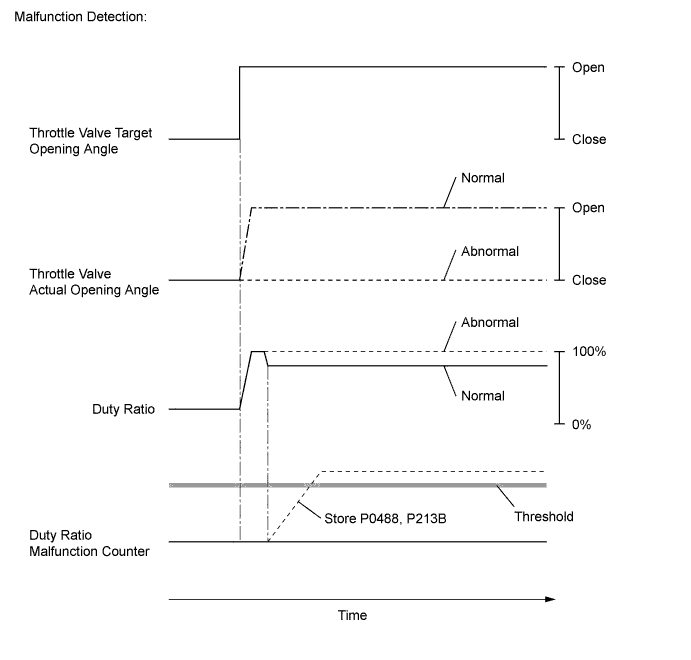
MONITOR DESCRIPTION
The ECM opens and closes the throttle valve by adjusting the current flowing to the rotary solenoid with a duty ratio. If the throttle valve does not move smoothly or is stuck, the duty ratio used during valve movement control increases or decreases greatly. The ECM will determine that the throttle valve is malfunctioning and illuminate the MIL.
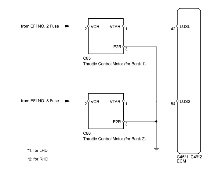
WIRING DIAGRAM
INSPECTION PROCEDURE
Note
After replacing the ECM, the new ECM needs registration Click here and initialization Click here.
Tech Tips
-
Although the DTC titles say Exhaust Gas Recirculation Throttle Position Control Range / Performance, these DTCs relate to the throttle valve
-
After warming up the engine, DTC P0488 and P213B can be stored when 1 second or more passes after quickly accelerating the engine from idling.
-
Read freeze frame data using the intelligent tester. Freeze frame data records the engine condition when malfunctions are detected. When troubleshooting, freeze frame data can help determine if the vehicle was moving or stationary, if the engine was warmed up or not, and other data from the time the malfunction occurred.
PROCEDURE
-
CHECK HARNESS AND CONNECTOR (THROTTLE CONTROL MOTOR POWER SOURCE)
-
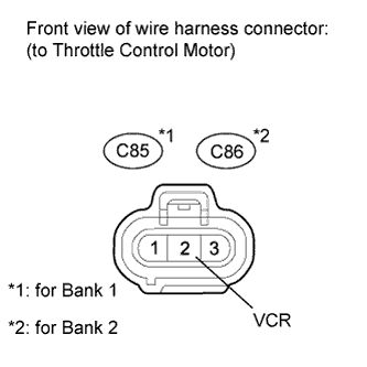
Disconnect the throttle control motor connector.
-
Measure the voltage according to the value(s) in the table below.
Standard Voltage for Bank 1 Tester Connection Switch Condition Specified Condition C85-2 (VCR) - Body ground Ignition switch ON 11 to 14 V for Bank 2 Tester Connection Switch Condition Specified Condition C86-2 (VCR) - Body ground Ignition switch ON 11 to 14 V
NG 
REPAIR OR REPLACE HARNESS OR CONNECTOR (THROTTLE CONTROL MOTOR - BATTERY) Click here
OK 
-
-
CHECK HARNESS AND CONNECTOR (GROUND CIRCUIT)
-
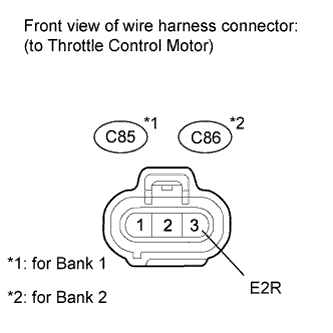
Disconnect the throttle control motor connector.
-
Measure the resistance according to the value(s) in the table below.
Standard Resistance (Check for Open) for Bank 1 Tester Connection Condition Specified Condition C85-3 (E2R) - Body ground Always Below 1 Ω for Bank 2 Tester Connection Condition Specified Condition C86-3 (E2R) - Body ground Always Below 1 Ω
NG
REPAIR OR REPLACE HARNESS OR CONNECTOR Click here
OK
-
-
CHECK HARNESS AND CONNECTOR (THROTTLE CONTROL MOTOR - ECM)
-
Disconnect the throttle control motor connector.
-
Disconnect the ECM connector.
-
Measure the resistance according to the value(s) in the table below.
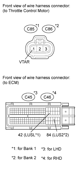
Standard Resistance (Check for Open) for Bank 1 (LHD) Tester Connection Condition Specified Condition C85-1 (VTAR) - C45-42 (LUSL) Always Below 1 Ω for Bank 2 (LHD) Tester Connection Condition Specified Condition C86-1 (VTAR) - C45-84 (LUS2) Always Below 1 Ω for Bank 1 (RHD) Tester Connection Condition Specified Condition C85-1 (VTAR) - C46-42 (LUSL) Always Below 1 Ω for Bank 2 (RHD) Tester Connection Condition Specified Condition C86-1 (VTAR) - C46-84 (LUS2) Always Below 1 Ω Standard Resistance (Check for Short) for Bank 1 (LHD) Tester Connection Condition Specified Condition C85-1 (VTAR) or C45-42 (LUSL) - Body ground Always 10 kΩ or higher for Bank 2 (LHD) Tester Connection Condition Specified Condition C86-1 (VTAR) or C45-84 (LUS2) - Body ground Always 10 kΩ or higher for Bank 1 (RHD) Tester Connection Condition Specified Condition C85-1 (VTAR) or C46-42 (LUSL) - Body ground Always 10 kΩ or higher for Bank 2 (RHD) Tester Connection Condition Specified Condition C86-1 (VTAR) or C46-84 (LUS2) - Body ground Always 10 kΩ or higher
NG
REPAIR OR REPLACE HARNESS OR CONNECTOR Click here
OK
-
-
REPLACE DIESEL THROTTLE BODY ASSEMBLY (for Bank 1 or Bank 2)
-
Replace the diesel throttle body assembly (for Bank 1 or Bank 2) Click here.
NEXT
-
-
CHECK WHETHER DTC OUTPUT RECURS
-
Clear DTCs Click here.
-
Connect the intelligent tester to the DLC3.
-
Turn the ignition switch to ON and turn the tester on.
-
Start the engine.
-
Over a period of 10 seconds or more, slowly raise the engine speed to 3000 rpm and lower it.
-
Enter the following menus: Powertrain / Engine / DTC.
-
Read the DTCs.
Result Result Proceed to P0488 and/or P213B is output A No DTC is output B
B
CONFIRM WHETHER MALFUNCTION HAS BEEN SUCCESSFULLY REPAIRED Click here
A
-
-
REPLACE ECM
-
Replace the ECM Click here.
NEXT
CONFIRM WHETHER MALFUNCTION HAS BEEN SUCCESSFULLY REPAIRED Click here
-
-
REPAIR OR REPLACE HARNESS OR CONNECTOR (THROTTLE CONTROL MOTOR - BATTERY)
NEXT
CONFIRM WHETHER MALFUNCTION HAS BEEN SUCCESSFULLY REPAIRED Click here
-
REPAIR OR REPLACE HARNESS OR CONNECTOR
NEXT
-
CONFIRM WHETHER MALFUNCTION HAS BEEN SUCCESSFULLY REPAIRED
-
Connect the intelligent tester to the DLC3.
-
Clear the DTCs Click here.
-
Turn the ignition switch off.
-
Start the engine.
-
Over a period of 10 seconds or more, slowly raise the engine speed to 3000 rpm and lower it.
-
Confirm that the DTC is not output again.
Tech Tips
Perform the following procedure using the tester to determine whether or not the DTC judgment has been carried out.
-
Enter the following menus: Powertrain / Engine / Utility / All Readiness.
-
Input DTC P0488 and/or P213B.
-
Check that STATUS is NORMAL. If STATUS is INCOMPLETE or UNKNOWN, over a period of 10 seconds or more, slowly raise the engine speed to 3000 rpm again and then idle the engine for 5 minutes.
-
NEXT 
END
-