ECD SYSTEM (w/o DPF), Diagnostic DTC:P0405, P0406, P0407, P0408

| DTC Code | DTC Name |
|---|---|
| P0405 | Exhaust Gas Recirculation Sensor "A" Circuit Low |
| P0406 | Exhaust Gas Recirculation Sensor "A" Circuit High |
| P0407 | Exhaust Gas Recirculation Sensor "B" Circuit Low |
| P0408 | Exhaust Gas Recirculation Sensor "B" Circuit High |
DESCRIPTION
The EGR valve position sensor is mounted on the EGR valve and used for detecting the lift amount of the valve. The lift amount detected by the sensor is provided to the ECM as feedback. The ECM then regulates the lift amount of the valve in accordance with engine running conditions.
| DTC Detection Drive Pattern | DTC Detection Condition | Trouble Area |
|---|---|---|
| Ignition switch ON for 5 seconds | No. 1 EGR valve position sensor output voltage is less than 0.1 V for 5 seconds (1 trip detection logic). |
|
| DTC Detection Drive Pattern | DTC Detection Condition | Trouble Area |
|---|---|---|
| Ignition switch ON for 5 seconds | No. 1 EGR valve position sensor output voltage is more than 4.9 V for 5 seconds (1 trip detection logic). |
|
| DTC Detection Drive Pattern | DTC Detection Condition | Trouble Area |
|---|---|---|
| Ignition switch ON for 5 seconds | No. 2 EGR valve position sensor output voltage is less than 0.1 V for 5 seconds (1 trip detection logic). |
|
| DTC Detection Drive Pattern | DTC Detection Condition | Trouble Area |
|---|---|---|
| Ignition switch ON for 5 seconds | No. 2 EGR valve position sensor output voltage is more than 4.9 V for 5 seconds (1 trip detection logic). |
|
MONITOR DESCRIPTION
When the output voltage of the EGR valve position sensor deviates from the normal operating range of 0.1 to 4.9 V for more than 5 seconds, the ECM interprets this as a malfunction of the sensor circuit, and illuminates the MIL.
WIRING DIAGRAM
Refer to DTC P0400 Click here.
INSPECTION PROCEDURE
Note
After replacing the ECM, the new ECM needs registration Click here and initialization Click here.
Tech Tips
-
Read freeze frame data using the intelligent tester. Freeze frame data records the engine condition when malfunctions are detected. When troubleshooting, freeze frame data can help determine if the vehicle was moving or stationary, if the engine was warmed up or not, and other data from the time the malfunction occurred.
-
Data List items "EGR Lift Sensor Volt %" and "EGR Lift Sensor Volt % #2" are values calculated by converting the EGR position sensor output voltage of 0 to 5 V to a percentage from 0 to 100%.
PROCEDURE
-
CHECK HARNESS AND CONNECTOR (POWER SOURCE)
-
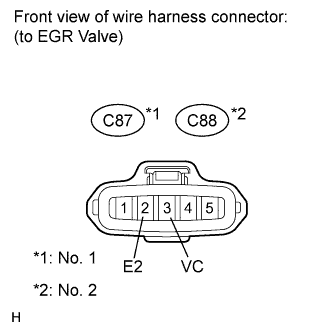
Disconnect the EGR valve connector.
-
Measure the voltage according to the value(s) in the table below.
Standard Voltage No. 1 Tester Connection Switch Condition Specified Condition C87-3 (VC) - C87-2 (E2) Ignition switch ON 4.5 to 5.5 V No. 2 Tester Connection Switch Condition Specified Condition C88-3 (VC) - C88-2 (E2) Ignition switch ON 4.5 to 5.5 V
NG 
CHECK HARNESS AND CONNECTOR (EGR VALVE POSITION SENSOR - ECM) Click here
OK 
-
-
INSPECT EGR VALVE ASSEMBLY (No. 1 or No. 2) (POSITION SENSOR)
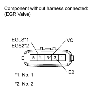
-
Disconnect the EGR valve connector.
-
Measure the resistance according to the value(s) in the table below.
Standard Resistance No. 1 Tester Connection Condition Specified Condition 3 (VC) - 2 (E2) 20°C (68°F) 2.45 to 4.55 kΩ 4 (EGLS) - 2 (E2) 20°C (68°F) 2.45 to 4.55 kΩ No. 2 Tester Connection Condition Specified Condition 3 (VC) - 2 (E2) 20°C (68°F) 2.45 to 4.55 kΩ 4 (EGS2) - 2 (E2) 20°C (68°F) 2.45 to 4.55 kΩ
NG
REPLACE EGR VALVE ASSEMBLY (No. 1 or No. 2) Click here
OK
-
-
CHECK HARNESS AND CONNECTOR (EGR VALVE POSITION SENSOR - ECM)
-
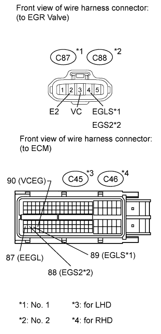
Disconnect the EGR valve connector.
-
Disconnect the ECM connector.
-
Measure the resistance according to the value(s) in the table below.
Standard Resistance (Check for Open) No. 1 (LHD) Tester Connection Condition Specified Condition C87-3 (VC) - C45-90 (VCEG) Always Below 1 Ω C87-4 (EGLS) - C45-89 (EGLS) Always Below 1 Ω C87-2 (E2) - C45-87 (EEGL) Always Below 1 Ω No. 2 (LHD) Tester Connection Condition Specified Condition C88-3 (VC) - C45-90 (VCEG) Always Below 1 Ω C88-4 (EGS2) - C45-88 (EGS2) Always Below 1 Ω C88-2 (E2) - C45-87 (EEGL) Always Below 1 Ω No. 1 (RHD) Tester Connection Condition Specified Condition C87-3 (VC) - C46-90 (VCEG) Always Below 1 Ω C87-4 (EGLS) - C46-89 (EGLS) Always Below 1 Ω C87-2 (E2) - C46-87 (EEGL) Always Below 1 Ω No. 2 (RHD) Tester Connection Condition Specified Condition C88-3 (VC) - C46-90 (VCEG) Always Below 1 Ω C88-4 (EGS2) - C46-88 (EGS2) Always Below 1 Ω C88-2 (E2) - C46-87 (EEGL) Always Below 1 Ω Standard Resistance (Check for Short) No. 1 (LHD) Tester Connection Condition Specified Condition C87-3 (VC) or C45-90 (VCEG) - Body ground Always 10 kΩ or higher C87-4 (EGLS) or C45-89 (EGLS) - Body ground Always 10 kΩ or higher No. 2 (LHD) Tester Connection Condition Specified Condition C88-3 (VC) or C45-90 (VCEG) - Body ground Always 10 kΩ or higher C88-4 (EGS2) or C45-88 (EGS2) - Body ground Always 10 kΩ or higher No. 1 (RHD) Tester Connection Condition Specified Condition C87-3 (VC) or C46-90 (VCEG) - Body ground Always 10 kΩ or higher C87-4 (EGLS) or C46-89 (EGLS) - Body ground Always 10 kΩ or higher No. 2 (RHD) Tester Connection Condition Specified Condition C88-3 (VC) or C46-90 (VCEG) - Body ground Always 10 kΩ or higher C88-4 (EGS2) or C46-88 (EGS2) - Body ground Always 10 kΩ or higher
NG
REPAIR OR REPLACE HARNESS OR CONNECTOR Click here
OK
-
-
REPLACE ECM
-
Replace the ECM Click here.
NEXT
CONFIRM WHETHER MALFUNCTION HAS BEEN SUCCESSFULLY REPAIRED Click here
-
-
REPLACE EGR VALVE ASSEMBLY (No. 1 or No. 2)
-
Replace the EGR valve assembly (No. 1 or No. 2) Click here.
NEXT
CONFIRM WHETHER MALFUNCTION HAS BEEN SUCCESSFULLY REPAIRED Click here
-
-
REPAIR OR REPLACE HARNESS OR CONNECTOR
NEXT
-
CONFIRM WHETHER MALFUNCTION HAS BEEN SUCCESSFULLY REPAIRED
-
Connect the intelligent tester to the DLC3.
-
Clear the DTCs Click here.
-
Turn the ignition switch off.
-
Turn the ignition switch to ON for 5 seconds.
-
Enter the following menus: Powertrain / Engine / DTC.
-
Confirm that the DTC is not output again.
NEXT 
END
-