FUEL SUPPLY PUMP INSTALLATION

Note
-
When replacing the injectors (including shuffling the injectors between the cylinders), common rail, cylinder head or intake manifold, it is necessary to replace the injection pipes with new ones.
-
w/ DPF:
When fuel lines are disconnected, air may enter the fuel lines, leading to engine starting trouble. Therefore, perform forced regeneration and bleed the air from the fuel lines Click here.
-
INSTALL FUEL SUPPLY PUMP
Note
Do not push the supply pump drive gear.
-
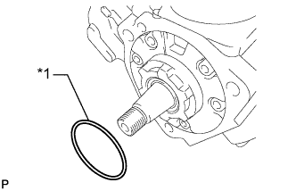
Text in Illustration *1 New O-Ring Install a new O-ring to the supply pump.
-
Apply a light coat of engine oil to the O-ring.
-
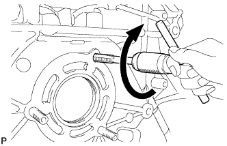
Using an 8 mm x 1.25 pitch tap, remove the adhesive from the timing gear case bolt hole.
-
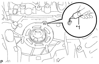
Text in Illustration *1 Adhesive Apply adhesive to 2 or more threads as shown in the illustration.
Adhesive Toyota Genuine Adhesive 1344, Three Bond 1344 or equivalent -
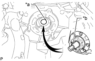
Text in Illustration *a Groove *b Set Key Align the set key on the drive shaft with the groove of the supply pump drive gear.
Note
Do not hold the supply pump by the parts indicated by the arrows in the illustration, as this may result in deformation, damage and fuel leakage.
-
Temporarily install the fuel supply pump with the 2 nuts.
-
Using a 6 mm hexagon wrench, install the bolt.
- Torque:
- 21 N*m { 214 kgf*cm, 15 ft.*lbf }
-
Tighten the 2 nuts.
- Torque:
- 21 N*m { 214 kgf*cm, 15 ft.*lbf }
-
Using a wrench, hold the crankshaft.
-
Install the set nut.
- Torque:
- 68 N*m { 693 kgf*cm, 50 ft.*lbf }
-
Turn the crankshaft 2 times, and check that there are no problems.
-
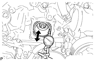
Using a dial indicator, check the thrust clearance of the supply pump drive shaft while moving the pump drive shaft gear back and forth.
Standard thrust clearance 0.05 to 0.30 mm (0.00197 to 0.0118 in.) If the clearance is not within the specified range, disassemble and reassemble the supply pump and pump drive shaft gear. Then repeat the step above.
-
Connect the fuel temperature sensor connector.
-
-
INSTALL NO. 1 FUEL PIPE
-
Install 2 new gaskets and the No. 1 fuel pipe with the union bolt.
- Torque:
- 17 N*m { 175 kgf*cm, 13 ft.*lbf }
-
-
INSTALL TIMING CHAIN COVER PLATE
-
Install a new gasket and the cover plate with the 4 bolts.
- Torque:
- 9.1 N*m { 93 kgf*cm, 81 in.*lbf }
-
-
INSTALL TIMING GEAR COVER INSULATOR (w/ Intercooler)
-
w/o Viscous Heater:
Install the timing gear cover insulator with the 2 bolts.
- Torque:
- 21 N*m { 214 kgf*cm, 15 ft.*lbf }
-
w/ Viscous Heater:
Install the timing gear cover insulator.
-
-
INSTALL FUEL TUBE SUB-ASSEMBLY (w/ DPF)
-
Attach the 3 clamps to install the fuel tube.
-
Connect the 3 fuel tube connectors Click here.
-
-
INSTALL NO. 1 WATER BY-PASS PIPE
-
INSTALL FUEL COOLER ASSEMBLY (w/o DPF)
-
INSTALL THERMOSTAT
-
INSTALL EGR VALVE ASSEMBLY WITH EGR COOLER (w/ EGR System)
-
CONNECT CABLE TO NEGATIVE BATTERY TERMINAL
Note
When disconnecting the cable, some systems need to be initialized after the cable is reconnected Click here.
-
Connect the cables to the negative (-) main battery and sub-battery terminals.
-
-
PERFORM FUEL SUPPLY PUMP INITIALIZATION