FUEL SUPPLY PUMP REMOVAL

Note
-
When replacing the injectors (including shuffling the injectors between the cylinders), common rail, cylinder head or intake manifold, it is necessary to replace the injection pipes with new ones.
-
w/ DPF:
When fuel lines are disconnected, air may enter the fuel lines, leading to engine starting trouble. Therefore, perform forced regeneration and bleed the air from the fuel lines.
-
PRECAUTION
Note
After turning the ignition switch off, waiting time may be required before disconnecting the cable from the battery terminal. Therefore, make sure to read the disconnecting the cable from the battery terminal notice before proceeding with work Click here.
-
DISCONNECT CABLE FROM NEGATIVE BATTERY TERMINAL
Note
When disconnecting the cable, some systems need to be initialized after the cable is reconnected Click here.
-
Disconnect the cables from the negative (-) main battery and sub-battery terminals.
-
-
REMOVE EGR VALVE ASSEMBLY WITH EGR COOLER (w/ EGR System)
-
REMOVE THERMOSTAT
-
REMOVE FUEL COOLER ASSEMBLY (w/o DPF)
-
REMOVE NO. 1 WATER BY-PASS PIPE
-
Text in Illustration *A w/ DPF *B w/o DPF Remove the union bolt, bolt, No. 1 water by-pass pipe and gasket.
-
-
REMOVE FUEL TUBE SUB-ASSEMBLY (w/ DPF)
-
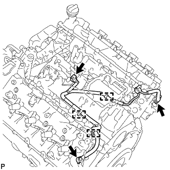
Disconnect the 3 fuel tube connectors Click here.
-
Detach the 3 clamps and remove the fuel tube.
-
-
REMOVE TIMING GEAR COVER INSULATOR (w/ Intercooler)
-
w/o Viscous Heater:
Remove the 2 bolts and timing gear cover insulator.
-
w/ Viscous Heater:
Remove the timing gear cover insulator.
-
-
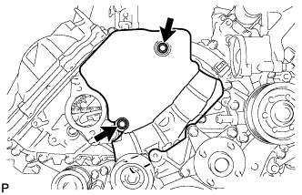
REMOVE TIMING CHAIN COVER PLATE
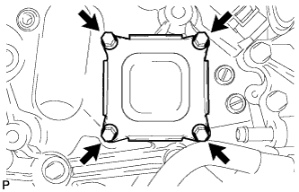
-
Remove the 4 bolts, cover plate and gasket.
-
-
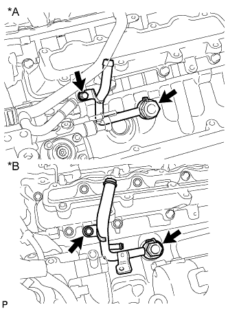
REMOVE NO. 1 FUEL PIPE
-
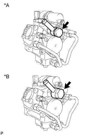
Text in Illustration *A w/ DPF *B w/o DPF Remove the union bolt, fuel pipe and 2 gaskets.
-
-
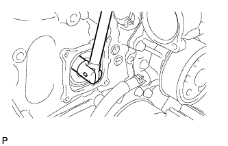
REMOVE FUEL SUPPLY PUMP
-
Using a wrench, hold the crankshaft.
Note
Do not turn the crankshaft counterclockwise.
If it is turned counterclockwise, check that the crankshaft pulley set bolt is not loose. If loose, tighten the bolt Click here.
- Torque:
- 108 N*m { 1101 kgf*cm, 80 ft.*lbf, or more }
-
Remove the set nut.
-
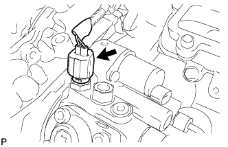
Disconnect the fuel temperature sensor connector.
-
Text in Illustration *A w/ DPF *B w/o DPF Using a 6 mm hexagon wrench, remove the bolt.
-
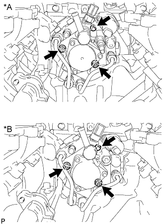
Loosen the 2 nuts.
-
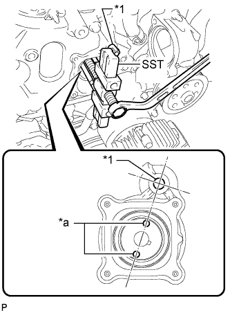
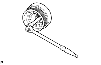
Text in Illustration *1 SST (No. 1 adapter) *a Service Hole Disconnect the pump from the supply pump drive gear.
-
Install SST (No. 1 adapter) to the timing chain cover.
- SST
- 09950-50013 ( 09951-05010, 09952-05010, 09953-05020, 09954-05031, 09955-05010 )
Note
Do not use any tools in this procedure.
-
Rotate the supply pump gear so that the service holes are aligned with SST (No. 1 adapter) as shown in the illustration.
-
Using SST, disconnect the pump from the supply pump drive gear.
Note
-
When removing or installing SST, do not push the supply pump gear.
-
Apply lubricant to the threads and tip of SST (center bolt) before using it.
-
-
-
Remove the 2 nuts.
Note
-
Do not hold the supply pump by the parts indicated by the arrows in the illustration, as this may result in deformation, damage and fuel leakage.
-
The pump must be kept horizontal.
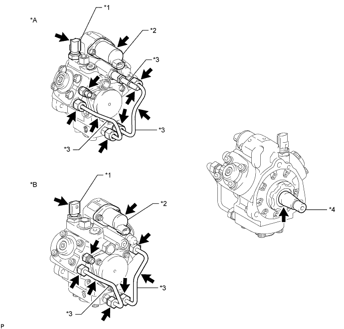
Text in Illustration *A w/ DPF *B w/o DPF *1 Fuel Temperature Sensor *2 Suction Control Valve *3 Fuel Pipe *4 Drive Shaft -
-
Remove the O-ring from the supply pump.
-