AIR SWITCHING VALVE (for Bank 1) INSTALLATION

-
INSTALL NO. 1 EMISSION CONTROL VALVE SET
-
Install the No. 1 emission control valve set with the 3 nuts.
- Torque:
- 21 N*m { 214 kgf*cm, 15 ft.*lbf }
-
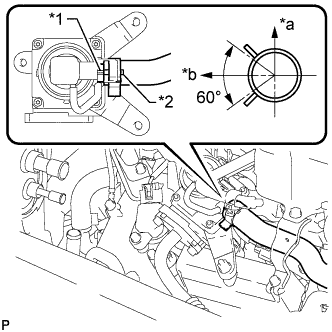
Text in Illustration *1 Rib *2 Paint Mark *a RH Side *b Top Align the paint mark with the rib and connect the No. 1 air hose.
Tech Tips
Make sure the direction of the hose clamp is as shown in the illustration.
-
Connect the No. 1 emission control valve set connector.
-
-
INSTALL AIR TUBE
-
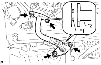
Text in Illustration *1 Claw *2 Air Tube Install 2 new gaskets.
Note
Make sure the gasket's claws are not caught between the No. 1 emission control valve set and air tube.
-
Install the air tube with the 2 bolts and 2 nuts.
- Torque:
- 10 N*m { 102 kgf*cm, 7 in.*lbf }
-
-
INSTALL AIR CLEANER CAP AND HOSE
-
Install the air cleaner cap and hose.
-
Install the air cleaner cap and hose with the bolt and fasten the 4 hook clamps.
- Torque:
- 5.0 N*m { 51 kgf*cm, 44 in.*lbf }
-
Tighten the clamp.
- Torque:
- 2.5 N*m { 25 kgf*cm, 22 in.*lbf }
-
Attach the clamp and connect the ventilation hose, vacuum hose and mass air flow meter connector.
-
-
-
INSTALL V-BANK COVER
-
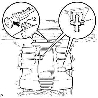
Text in Illustration *1 Pin *2 Hook Attach the 2 V-bank cover hooks to the bracket. Then align the 2 V-bank cover grommets with the 2 pins and press down on the V-bank cover to attach the pins.
-