BLACK OUT TAPE (for Rear Door) REMOVAL

Tech Tips
-
Use the same procedure for the LH side and RH side.
-
The following procedure is for the LH side.
-
PRECAUTION
Note
After turning the engine switch off, waiting time may be required before disconnecting the cable from the negative (-) battery terminal. Therefore, make sure to read the disconnecting the cable from the negative (-) battery terminal notices before proceeding with work Click here.
-
DISCONNECT CABLE FROM NEGATIVE BATTERY TERMINAL
Note
When disconnecting the cable, some systems need to be initialized after the cable is reconnected Click here.
-
REMOVE REAR DOOR INSIDE HANDLE BEZEL PLUG
-
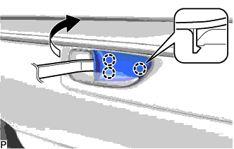
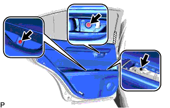
Using a moulding remover, disengage the 3 claws and remove the rear door inside handle bezel plug as shown in the illustration.
-
-
REMOVE REAR POWER WINDOW REGULATOR SWITCH ASSEMBLY WITH REAR DOOR ARMREST BASE PANEL
-
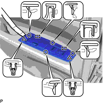
Using a moulding remover, disengage the 2 clips, 4 claws and 2 guides as shown in the illustration.
-
Disconnect the connector and remove the rear power window regulator switch assembly with rear door armrest base panel.
-
-
REMOVE DOOR PULL HANDLE COVER
-
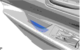
Remove the door pull handle cover.
-
-
REMOVE REAR DOOR NO. 1 STIFFENER CUSHION
-
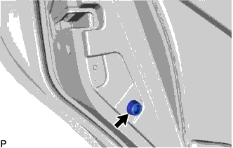
Remove the screw and rear door No. 1 stiffener cushion.
-
-
REMOVE COURTESY LIGHT ASSEMBLY
-
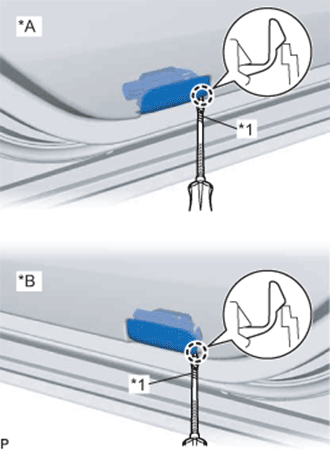
Text in Illustration *A for LH Side *B for RH Side *1 Protective Tape Using a screwdriver with its tip wrapped with protective tape, disengage the claw.
-
Disconnect the connector and remove the courtesy light assembly.
-
-
REMOVE REAR DOOR TRIM BOARD SUB-ASSEMBLY
-
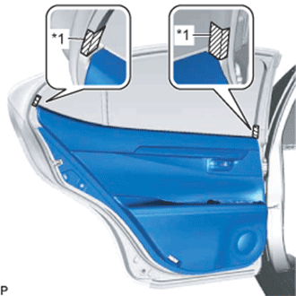
Text in Illustration *1 Protective Tape Put protective tape around the rear door panel.
-
Remove the 3 screws.
-
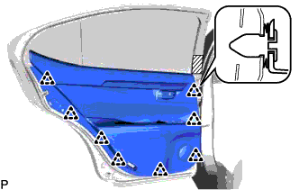
Using a clip remover, disengage the 8 clips.
-
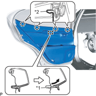
Text in Illustration *1 Reference Boss *2 Rear Door Inner Glass Weatherstrip Pull out the rear door trim board sub-assembly in the direction indicated by the arrow as shown in the illustration.
-
Disengage the reference boss from the rear door panel.
-
Using a screwdriver, disengage the 4 claws and disconnect the rear door trim board sub-assembly.
-
w/ Illumination:
-
Disconnect the connector.
-
-
for 15 Speakers:
-
Disconnect the connector.
-
-
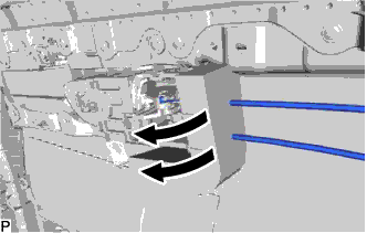
Disconnect the rear door lock remote control cable assembly and rear door inside locking cable assembly to remove the rear door trim board sub-assembly.
-
Remove the No. 1 door scuff plate clamp.
-
-
REMOVE REAR DOOR INNER GLASS WEATHERSTRIP
-
Remove the rear door inner glass weatherstrip.
-
-
REMOVE REAR SIDE CURTAIN ASSEMBLY (w/ Rear Door Sunshade)
-
Disengage the 2 clips and 2 claws and remove the rear side curtain assembly.
-
-
REMOVE REAR DOOR ARMREST SET BRACKET
-
Remove the 2 screws and rear door armrest set bracket.
-
-
REMOVE REAR DOOR SERVICE HOLE COVER
-
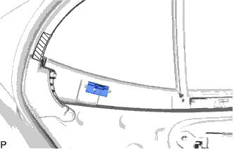
Disconnect the connector.
-
Disengage the 2 clamps and remove the rear door service hole cover.
Tech Tips
Remove any remaining butyl tape from the rear door door.
-
-
DISCONNECT REAR DOOR WEATHERSTRIP
-
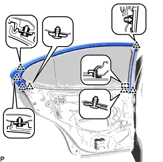
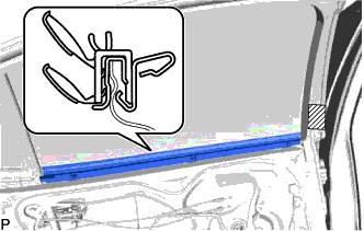
Disengage the 7 clips and guide and disconnect the rear door weatherstrip.
-
-
REMOVE REAR DOOR GLASS RUN
-
Remove the rear door glass run.
-
-
REMOVE REAR DOOR NO. 1 VENT SEAL
-
Remove the rear door No. 1 vent seal.
-
-
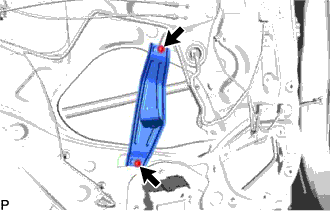
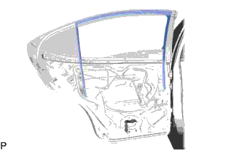
REMOVE REAR DOOR LOWER WINDOW FRAME SUB-ASSEMBLY
-
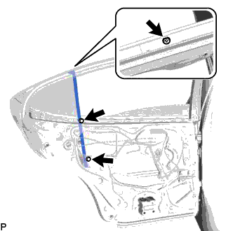
Remove the 2 bolts and screw, and rear door lower window frame sub-assembly.
Note
When the rear door lower window frame sub-assembly is removed, do not allow the rear door quarter window glass to fall.
-
-
REMOVE REAR DOOR QUARTER WINDOW GLASS
-
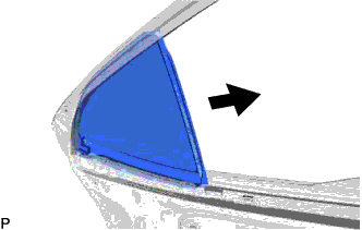
Remove the rear door quarter window glass with the rear door quarter window weatherstrip as shown in the illustration.
-
Remove the rear door quarter window glass from the rear door quarter window weatherstrip.
-
-
REMOVE REAR DOOR GLASS ASSEMBLY
-
Remove the rear door glass assembly from the rear door window regulator assembly as shown in the illustration.
Note
Do not damage the door glass assembly.
-
-
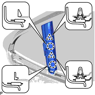
REMOVE REAR DOOR FRAME GARNISH
-
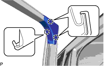
Disengage the 3 claws and remove the rear door frame garnish.
-
-
REMOVE CURTAIN HOOK (w/ Rear Door Sunshade)
-
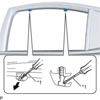
Text in Illustration *1 Protective Tape Using a screwdriver, push out the 2 pins as shown in the illustration.
Tech Tips
Tape the screwdriver tip before use.
-
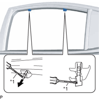
Text in Illustration *1 Protective Tape Using a screwdriver, disengage the 2 pins.
Tech Tips
Tape the screwdriver tip before use.
-
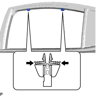
Disengage the 4 claws and remove the 2 curtain hooks as shown in the illustration.
-
-
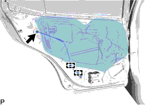
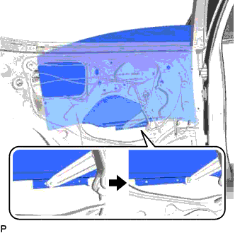
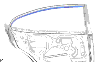
REMOVE REAR INNER BLACK OUT TAPE
-
Using a heat light, heat the rear inner black out tape and vehicle body.
Heating Temperature Item Temperature Vehicle Body and Rear Inner Black Out Tape 40 to 60°C (104 to 140°F) Note
Do not heat the vehicle body excessively.
-
Pull back on one of the ends of the rear inner black out tape to remove it.
Tech Tips
When pulling on the black out tape, pull it parallel to the body.
-
-
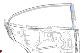
REMOVE FRONT INNER BLACK OUT TAPE
-
Using a heat light, heat the front inner black out tape and vehicle body.
Heating Temperature Item Temperature Vehicle Body and Front Inner Black Out Tape 40 to 60°C (104 to 140°F) Note
Do not heat the vehicle body excessively.
-
Pull back on one of the ends of the front inner black out tape to remove it.
Tech Tips
When pulling on the black out tape, pull it parallel to the body.
-