HEADLIGHT LEVELING ECU INSTALLATION

-
INSTALL HEADLIGHT LEVELING ECU ASSEMBLY
-
Install the headlight leveling ECU assembly with the bolt.
- Torque:
- 5.5 N*m { 56 kgf*cm, 49 in.*lbf }
-
Engage the clamp.
-
Connect the connector.
-
-
INSTALL ECU INTEGRATION BOX RH (for RHD)
-
Install the ECU integration box RH with the bolt and 2 nuts.
- Torque:
- Nut
- 5.5 N*m { 56 kgf*cm, 49 in.*lbf }
- Bolt
- 7.5 N*m { 76 kgf*cm, 66 in.*lbf }
-
Connect each connector.
-
-
INSTALL LOWER NO. 1 INSTRUMENT PANEL AIRBAG ASSEMBLY (for RHD)
-
Check that the engine switch is off.
-
Check that the cable is disconnected from the negative (-) battery terminal.
CAUTION:
Wait at least 90 seconds after disconnecting the cable from the negative (-) battery terminal to disable the SRS system.
-
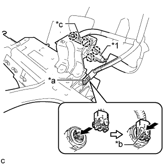
Text in Illustration *1 No. 1 Interior Illumination Light Assembly *a Airbag Connector *b Airbag Connector Lock *c DLC3 Connect the airbag connector to the lower No. 1 instrument panel airbag assembly.
Note
When connecting any airbag connector, take care not to damage the airbag wire harness.
-
Push in the airbag connector lock to install the airbag connector.
-
Engage the 2 claws to connect the DLC3.
-
Engage the 2 claws to connect the No. 1 interior illumination light assembly.
-
Engage the 2 hooks to temporarily install the lower No. 1 instrument panel airbag assembly.
-
Install the 4 bolts.
- Torque:
- 10 N*m { 102 kgf*cm, 7 ft.*lbf }
Note
Confirm that the lower No. 1 instrument panel airbag assembly is installed securely without any excessive gaps and is not protruding outward.
-
-
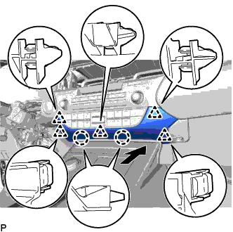
INSTALL LOWER NO. 1 INSTRUMENT PANEL FINISH PANEL
-
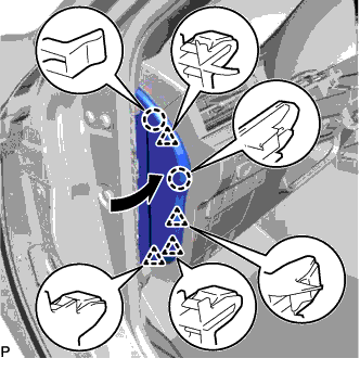
for LHD:
-
Connect each connector and engage each clamp.
-
Engage the 12 claws, 2 clips and guide.
-
Install the lower No. 1 instrument panel finish panel with the 2 bolts <B>.
-
-
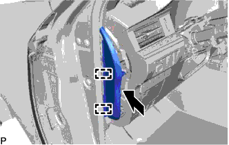
for RHD:
-
Connect each connector and engage each clamp.
-
Engage the 6 claws, 3 clips and guide.
-
Install the lower No. 1 instrument panel finish panel with the 2 bolts <B>.
-
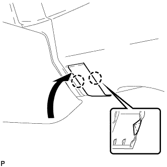
Engage the 2 claws to close the cover as shown in the illustration.
-
-
-
CONNECT HOOD LOCK CONTROL LEVER SUB-ASSEMBLY
-
Engage the claw and 2 guides to connect the hood lock control lever sub-assembly.
-
-
INSTALL INSTRUMENT SIDE PANEL
-
Engage the 2 guides as shown in the illustration.
-
Engage the 2 claws and 4 clips to install the instrument side panel LH as shown in the illustration.
-
-
INSTALL FRONT DOOR OPENING TRIM COVER
-
Engage the guide.
-
Engage the 3 claws to install the front door opening trim cover LH.
-
-
INSTALL COWL SIDE TRIM BOARD
-
Engage the clip and claw.
-
Install the cowl side trim board LH with the clip.
-
-
INSTALL FRONT DOOR SCUFF PLATE
-
Engage the 10 claws to install the front door scuff plate LH.
-
-
INSTALL LOWER CENTER INSTRUMENT PANEL FINISH PANEL
-
Engage the 2 claws and 5 clips to install the lower center instrument panel finish panel as shown in the illustration.
-
-
CONNECT CABLE TO NEGATIVE BATTERY TERMINAL (for RHD)
Note
When disconnecting the cable, some systems need to be initialized after the cable is reconnected Click here.
-
INSPECT SRS WARNING LIGHT (for RHD)
-
INITIALIZE HEIGHT CONTROL SENSOR SIGNAL
-
ADJUST HEADLIGHT AIMING