HEADLIGHT LEVELING ECU REMOVAL

-
PRECAUTION (for RHD)
Note
After turning the engine switch off, waiting time may be required before disconnecting the cable from the negative (-) battery terminal. Therefore, make sure to read the disconnecting the cable from the negative (-) battery terminal notices before proceeding with work Click here.
-
DISCONNECT CABLE FROM NEGATIVE BATTERY TERMINAL (for RHD)
CAUTION:
Wait at least 90 seconds after disconnecting the cable from the negative (-) battery terminal to disable the SRS system.
Note
When disconnecting the cable, some systems need to be initialized after the cable is reconnected Click here.
-
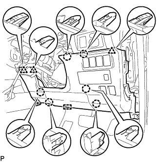
REMOVE LOWER CENTER INSTRUMENT PANEL FINISH PANEL
-
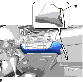
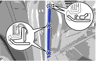
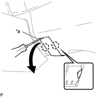
Text in Illustration *a Lower Center Instrument Panel Finish Panel Hole Insert a moulding remover as shown in the illustration.
-
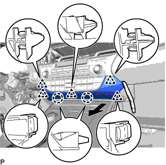
Using a moulding remover, disengage the 2 claws and 5 clips and remove the lower center instrument panel finish panel as shown in the illustration.
-
-
REMOVE FRONT DOOR SCUFF PLATE
-
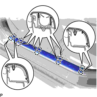
Disengage the 10 claws and remove the front door scuff plate LH.
-
-
REMOVE COWL SIDE TRIM BOARD
-
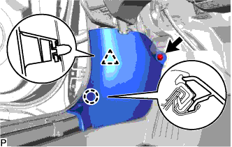
Remove the clip.
-
Disengage the claw and clip, and remove the cowl side trim board LH.
-
-
REMOVE FRONT DOOR OPENING TRIM COVER
-
Disengage the 3 claws.
-
Disengage the guide and remove the front door opening trim cover LH.
-
-
REMOVE INSTRUMENT SIDE PANEL
-
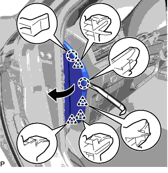
Using a moulding remover, disengage the 2 claws and 4 clips as shown in the illustration.
-
Disengage the 2 guides and remove the instrument side panel LH as shown in the illustration.
-
-
DISCONNECT HOOD LOCK CONTROL LEVER SUB-ASSEMBLY
-
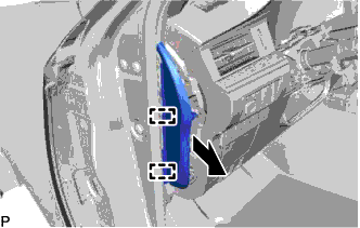
Disengage the claw and 2 guides to disconnect the hood lock control lever sub-assembly.
-
-
REMOVE LOWER NO. 1 INSTRUMENT PANEL FINISH PANEL
-
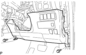
for LHD:
-
Remove the 2 bolts <B>.
-
Disengage the 12 claws, 2 clips and guide.
-
Disconnect each connector and disengage each clamp to remove the lower No. 1 instrument panel finish panel.
-
-
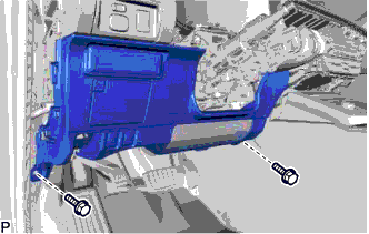
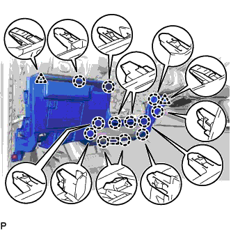
for RHD:
-
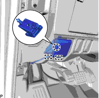
Text in Illustration *a Protective Tape Using a screwdriver, disengage the 2 claws and open the cover.
Tech Tips
Tape the screwdriver tip before use.
-
Remove the 2 bolts <B>.
-
Disengage the 6 claws, 3 clips and guide.
-
Disconnect each connector and disengage each clamp to remove the lower No. 1 instrument panel finish panel.
-
-
-
REMOVE LOWER NO. 1 INSTRUMENT PANEL AIRBAG ASSEMBLY (for RHD)
CAUTION:
When storing the lower No. 1 instrument panel airbag assembly, keep the airbag deployment side facing upward.
-
Check that the engine switch is off.
-
Check that the cable is disconnected from the negative (-) battery terminal.
CAUTION:
Wait at least 90 seconds after disconnecting the cable from the negative (-) battery terminal to disable the SRS system.
-
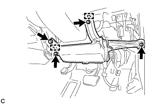
Remove the 4 bolts.
-
Disengage the 2 hooks to separate the lower No. 1 instrument panel airbag assembly.
Note
When removing the lower No. 1 instrument panel airbag assembly, do not pull the airbag wire harness.
-
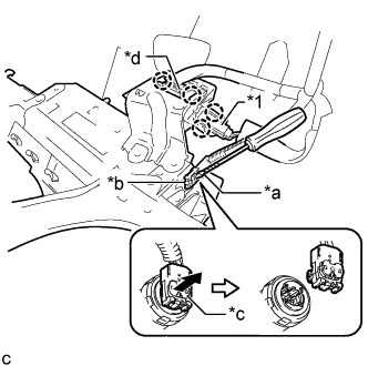
Text in Illustration *1 No. 1 Interior Illumination Light Assembly *a Protective Tape *b Airbag Connector *c Airbag Connector Lock *d DLC3 Disengage the 2 claws to disconnect the DLC3.
-
Disengage the 2 claws to disconnect the No. 1 interior illumination light assembly.
-
Using a screwdriver with its tip wrapped with protective tape, release the airbag connector lock.
-
Disconnect the airbag connector to remove the lower No. 1 instrument panel airbag assembly.
Note
When disconnecting any airbag connector, take care not to damage the airbag wire harness.
-
-
REMOVE ECU INTEGRATION BOX RH (for RHD)
-
Disconnect each connector.
-
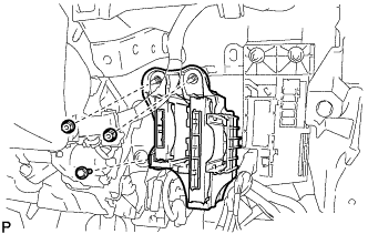
Remove the bolt, 2 nuts and ECU integration box RH.
-
-
REMOVE HEADLIGHT LEVELING ECU ASSEMBLY
-
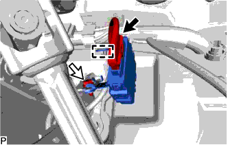
Disconnect the connector.
-
Disengage the clamp.
-
Remove the bolt and headlight leveling ECU assembly.
-