HAZARD WARNING SWITCH INSTALLATION

-
PRECAUTION (w/ Multi-display)
Note
When installing the hard disk drive, eliminate static electricity by touching the vehicle body to prevent components from being damaged.
-
INSTALL RADIO RECEIVER ASSEMBLY (HAZARD SWITCH) (w/o Multi-display)
-
INSTALL NO. 2 RADIO BRACKET (w/o Multi-display)
-
Install the No. 2 radio bracket with the 4 screws.
-
-
INSTALL NO. 1 RADIO BRACKET (w/o Multi-display)
-
Install the No. 1 radio bracket with the 4 screws.
-
-
INSTALL MULTI-MEDIA MODULE RECEIVER ASSEMBLY (HAZARD SWITCH) (w/ Multi-display)
-
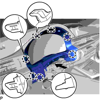
INSTALL HARD DISK DRIVE (w/ Multi-display)
-
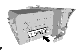
Insert the hard disk drive in the direction shown by the arrow in the illustration to install it.
-
Engage the 2 guides to temporarily install the cover.
-
Install the cover with the 2 screws.
-
-
INSTALL NO. 2 RADIO BRACKET (w/ Multi-display)
-
Install the No. 2 radio bracket with the 4 screws.
-
-
INSTALL NO. 1 RADIO BRACKET (w/ Multi-display)
-
Install the No. 1 radio bracket with the 4 screws.
-
-
INSTALL RADIO RECEIVER ASSEMBLY WITH BRACKET (w/o Multi-display)
-
Connect each connector.
-
Engage the 2 clips and 2 claws to temporarily install the radio receiver assembly with bracket.
-
Install the radio receiver assembly with bracket with the 4 bolts.
-
-
INSTALL MULTI-MEDIA MODULE RECEIVER ASSEMBLY WITH BRACKET (w/ Multi-display)
-
Connect each connector.
-
Engage the 2 clips and 2 claws to the vehicle body to temporarily install the multi-media module receiver assembly with bracket.
-
Install the multi-media module receiver assembly with bracket with the 4 bolts.
-
-
INSTALL LOWER CENTER INSTRUMENT PANEL FINISH PANEL
-
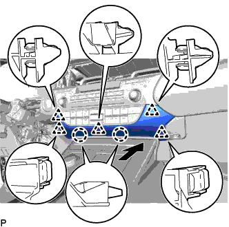
Engage the 2 claws and 5 clips to install the lower center instrument panel finish panel as shown in the illustration.
-
-
INSTALL NO. 2 INSTRUMENT PANEL REGISTER ASSEMBLY
-
Connect the connector.
-
Engage the 11 claws and clip to install the No. 2 instrument panel register assembly.
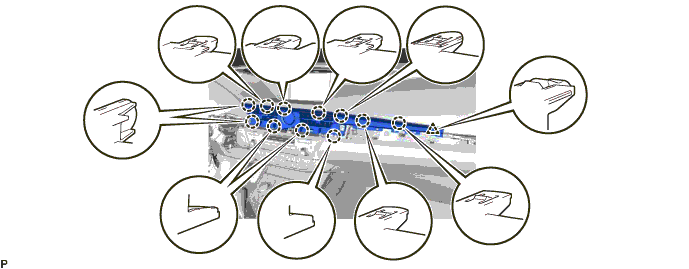
Note
When installing the No. 2 instrument panel register assembly, check that the wire harness is not caught between the No. 2 instrument panel register assembly and duct.
-
-
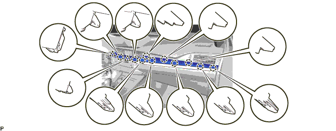
INSTALL CENTER INSTRUMENT CLUSTER FINISH PANEL GARNISH
-
Connect the connector.
-
Engage the 10 claws and 2 clips to install the center instrument cluster finish panel garnish.
-
-
INSTALL INSTRUMENT CLUSTER FINISH PANEL SUB-ASSEMBLY
-
Connect the connector.
-
Engage the 5 claws and 2 guides as shown in the illustration.
-
Install the instrument cluster finish panel sub-assembly with the 2 screws <E>.
-
-
CONNECT CABLE TO NEGATIVE BATTERY TERMINAL (w/ Multi-display)
Note
When disconnecting the cable, some systems need to be initialized after the cable is reconnected Click here.
-
INSPECT HARD DISK DRIVE (w/ Multi-display)
-
PERFORM FOR MULTI-MEDIA MODULE RECEIVER ASSEMBLY INITIALIZATION (w/ Parking Assist Monitor System)
Tech Tips
When replacing the navigation ECU sub-assembly, perform parking assist monitor system initialization Click here.
-
CUSTOMIZE POWER TILT AND POWER TELESCOPIC STEERING COLUMN SYSTEM
Tech Tips
The following items can be customized.
Note
-
When the customer requests a change in a function, first make sure that the function can be customized.
-
Record the current settings before customizing.
-
Customizing with the GTS
-
Connect the GTS to the DLC3.
-
Turn the engine switch on (IG).
-
Turn the GTS on.
-
Enter the following menus: Body Electrical / Tilt & Telescopic / Utility / Customize.
-
Select the setting by referring to the table below.
Tilt & Telescopic Tester Display Default Content Setting Relevant ECU Autoaway/Return function ON Turn on/off the auto away/return function ON/OFF Multiplex tilt and telescopic ECU
-
-