HAZARD WARNING SWITCH REMOVAL

-
PRECAUTION (w/ Navigation System)
Note
-
may be required before disconnecting the cable from the negative (-) battery terminal. Therefore, make sure to read the disconnecting the cable from the negative (-) battery terminal notices before proceeding with work Click here.
-
A Hard Disk Drive (HDD) is built into the multimedia module receiver assembly to store map and other data, and is used for the navigation system. Therefore, care must be taken for the following points when handling the multi-media module receiver assembly.
-
When removing the hard disk drive, eliminate static electricity by touching the vehicle body to prevent components from being damaged.
-
-
CUSTOMIZE POWER TILT AND POWER TELESCOPIC STEERING COLUMN SYSTEM
Tech Tips
The following items can be customized.
Note
-
When the customer requests a change in a function, first make sure that the function can be customized.
-
Record the current settings before customizing.
-
Customizing with the GTS
-
Connect the GTS to the DLC3.
-
Turn the engine switch on (IG).
-
Turn the GTS on.
-
Enter the following menus: Body Electrical / Tilt & Telescopic / Utility / Customize.
-
Select the setting by referring to the table below.
Tilt & Telescopic Tester Display Default Content Setting Relevant ECU Autoaway/Return function ON Turn on/off the auto away/return function ON/OFF Multiplex tilt and telescopic ECU
-
-
-
DISCONNECT CABLE FROM NEGATIVE BATTERY TERMINAL (w/ Navigation System)
Note
When disconnecting the cable, some systems need to be initialized after the cable is reconnected Click here.
-
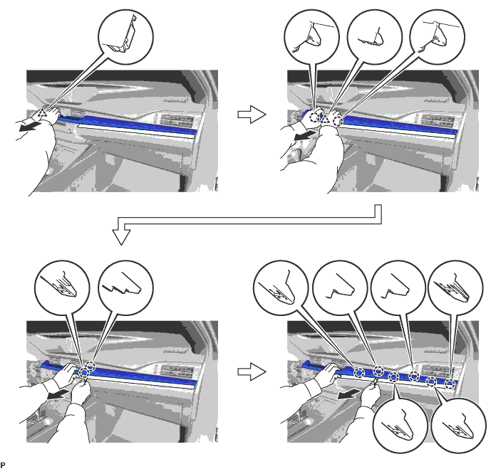
REMOVE INSTRUMENT CLUSTER FINISH PANEL SUB-ASSEMBLY
-
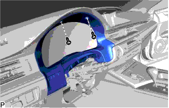
Remove the 2 screws <E>.
-
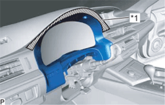
Text in Illustration *1 Protective Tape Apply protective tape to the area shown in the illustration.
-
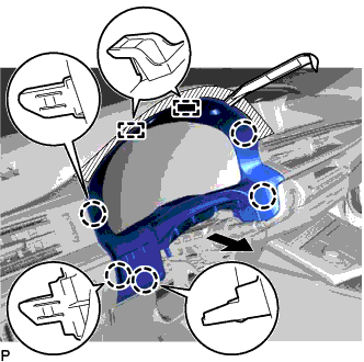
Using a moulding remover, disengage the 5 claws and 2 guides as shown in the illustration.
-
Disconnect the connector to remove the instrument cluster finish panel sub-assembly.
-
-
REMOVE CENTER INSTRUMENT CLUSTER FINISH PANEL GARNISH
-
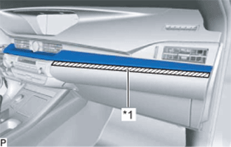
Text in Illustration *1 Protective Tape Apply protective tape to the area shown in the illustration.
-
Using a moulding remover, disengage the 10 claws and 2 clips as shown in the illustration.
-
Disconnect the connector to remove the center instrument cluster finish panel garnish.
-
-
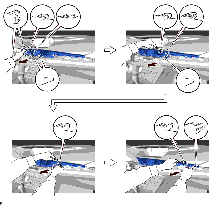
REMOVE NO. 2 INSTRUMENT PANEL REGISTER ASSEMBLY
-
Using a moulding remover, disengage the 11 claws and clip as shown in the illustration.
-
Disconnect the connector to remove the No. 2 instrument panel register assembly.
-
-
REMOVE LOWER CENTER INSTRUMENT PANEL FINISH PANEL
-
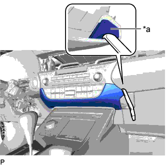
Text in Illustration *a Lower Center Instrument Panel Finish Panel Hole Insert a moulding remover as shown in the illustration.
-
Disengage the 2 claws and 5 clips and remove the lower center instrument panel finish panel as shown in the illustration.
-
-
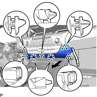
REMOVE RADIO RECEIVER ASSEMBLY WITH BRACKET (w/o Navigation System)
-
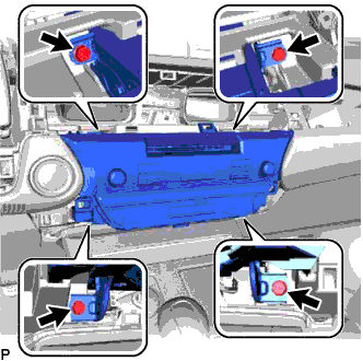
Remove the 4 bolts.
-
Pull the radio receiver assembly with bracket toward the rear of the vehicle and disengage the 2 clips and 2 claws.
-
Disconnect each connector and remove the radio receiver assembly with bracket.
-
-
REMOVE MULTI-MEDIA MODULE RECEIVER ASSEMBLY WITH BRACKET (w/ Navigation System)
-
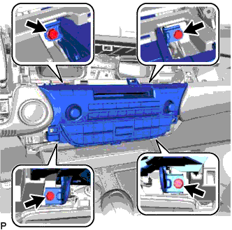
Remove the 4 bolts.
-

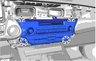
Pull the multi-media module receiver assembly with bracket toward the rear of the vehicle and disengage the 2 clips and 2 claws.
-
Disconnect each connector and remove the multi-media module receiver assembly with bracket.
-
-
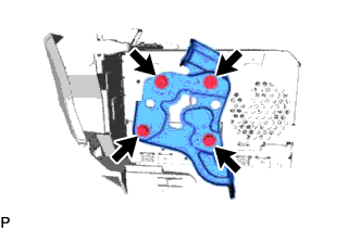
REMOVE NO. 1 RADIO BRACKET (w/o Navigation System)
-
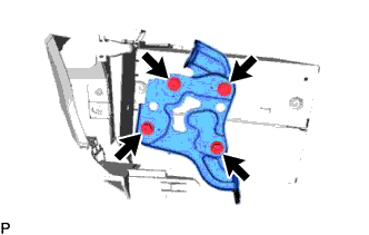
Remove the 4 screws and No. 1 radio bracket.
-
-
REMOVE NO. 2 RADIO BRACKET (w/o Navigation System)
-
Remove the 4 screws and No. 2 radio bracket.
-
-
REMOVE RADIO RECEIVER ASSEMBLY (HAZARD SWITCH) (w/o Navigation System)
-
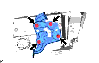
REMOVE NO. 1 RADIO BRACKET (w/ Navigation System)
-
Remove the 4 screws and No. 1 radio bracket.
-
-
REMOVE NO. 2 RADIO BRACKET (w/ Navigation System)
-
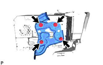
Remove the 4 screws and No. 2 radio bracket.
-
-
REMOVE HARD DISK DRIVE (w/ Navigation System)
-
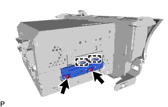
Remove the 2 screws.
-
Disengage the 2 guides to remove the cover.
-
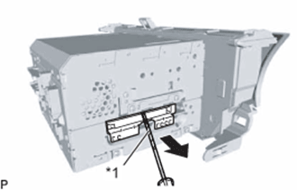
Text in Illustration *1 Protective Tape Using a screwdriver with its tip wrapped with protective tape, slide the hard disk drive in the direction shown by the arrow to remove it.
-
-
REMOVE MULTI-MEDIA MODULE RECEIVER ASSEMBLY (HAZARD SWITCH) (w/ Navigation System)