LIGHTING SYSTEM Taillight Relay Circuit
DESCRIPTION
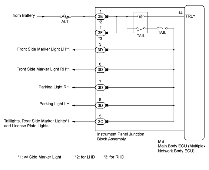
The main body ECU (multiplex network body ECU) controls the operation of the TAIL relay.
WIRING DIAGRAM
INSPECTION PROCEDURE
Note
-
Inspect the fuses for circuits related to this system before performing the following inspection procedure.
-
If the main body ECU (multiplex network body ECU) is replaced, refer to Service Bulletin.
PROCEDURE
-
PERFORM ACTIVE TEST USING GTS
-
Connect the GTS to the DLC3.
-
Turn the engine switch on (IG).
-
Turn the GTS on.
-
Enter the following menus: Body Electrical / Main Body / Active Test.
-
Check that the relay operates.
Main Body Tester Display Test Part Control Range Diagnostic Note Taillight Relay Taillight relay ON/OFF - OK Taillight relay operates. (Taillights illuminate.)
NG 
CHECK HARNESS AND CONNECTOR (BATTERY - INSTRUMENT PANEL JUNCTION BLOCK ASSEMBLY) Click here
OK 
PROCEED TO NEXT SUSPECTED AREA SHOWN IN PROBLEM SYMPTOMS TABLE Click here
-
-
CHECK HARNESS AND CONNECTOR (BATTERY - INSTRUMENT PANEL JUNCTION BLOCK ASSEMBLY)
-
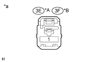
Text in Illustration *A for LHD *B for RHD *a Front view of wire harness connector
(to Instrument Panel Junction Block Assembly)
Disconnect the 3E*1 or 3F*2 instrument panel junction block assembly connector.
-
Measure the voltage according to the value(s) in the table below.
Standard Voltage Tester Connection Condition Specified Condition 3E-1*1 - Body ground Always 11 to 14 V 3F-1*2 - Body ground Always 11 to 14 V
-
*1: for LHD
-
*2: for RHD
-
NG 
REPAIR OR REPLACE HARNESS OR CONNECTOR
OK 
-
-
INSPECT INSTRUMENT PANEL JUNCTION BLOCK ASSEMBLY
-
Remove the instrument panel junction block assembly Click here.
-
Remove the main body ECU (multiplex network body ECU) from the instrument panel junction block assembly.
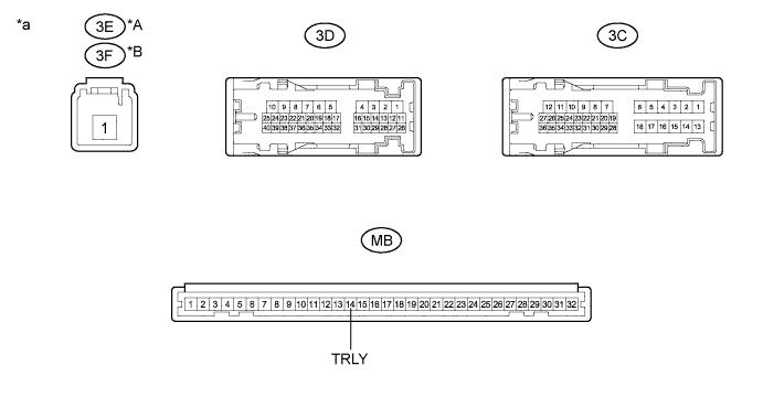
Text in Illustration *A for LHD *B for RHD *a Component without harness connected
(Instrument Panel Junction Block Assembly)
- - -
Connect a positive (+) lead from the battery to terminal 3E-1*2 or 3F-1*3.
-
Connect a negative (-) lead from the battery to terminal MB-14 (TRLY).
-
Measure the voltage according to the value(s) in the table below.
Standard Voltage Tester Connection Condition Specified Condition 3D-3*1 - Battery negative terminal Always 11 to 14 V 3D-6*1 - Battery negative terminal Always 11 to 14 V 3D-7 - Battery negative terminal Always 11 to 14 V 3D-8 - Battery negative terminal Always 11 to 14 V 3C-5 - Battery negative terminal Always 11 to 14 V
-
*1: w/ Side Marker Light
-
*2: for LHD
-
*3: for RHD
-
NG
REPLACE INSTRUMENT PANEL JUNCTION BLOCK ASSEMBLY Click here
OK
REPLACE MAIN BODY ECU (MULTIPLEX NETWORK BODY ECU) Click here
-