LIGHTING SYSTEM Hazard Warning Switch Circuit
DESCRIPTION
The combination meter assembly receives the hazard switch ON signal and controls the operation of the hazard warning lights.
WIRING DIAGRAM
-
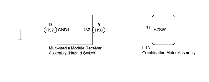
w/ Navigation System:
-
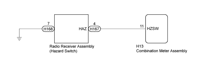
w/o Navigation System:
INSPECTION PROCEDURE
PROCEDURE
-
READ VALUE USING GTS
-
Connect the GTS to the DLC3.
-
Turn the engine switch on (IG).
-
Turn the GTS on.
-
Enter the following menus: Body Electrical / Combination Meter / Data List.
-
Read the display on the GTS.
Combination Meter Tester Display Measurement Item/Range Normal Condition Diagnostic Note Hazard Flasher Switch Hazard switch signal/ON or OFF ON: Hazard switch on
OFF: Hazard switch off
- OK Normal conditions listed above are displayed. Result Result Proceed to OK A NG (w/ Navigation System) B NG (w/o Navigation System) C
B 
INSPECT MULTI-MEDIA MODULE RECEIVER ASSEMBLY (HAZARD SWITCH) Click here
C
INSPECT RADIO RECEIVER ASSEMBLY (HAZARD SWITCH) Click here
A 
PROCEED TO NEXT SUSPECTED AREA SHOWN IN PROBLEM SYMPTOMS TABLE Click here
-
-
INSPECT MULTI-MEDIA MODULE RECEIVER ASSEMBLY (HAZARD SWITCH)
-
Remove the multi-media module receiver assembly Click here.
-
Inspect the multi-media module receiver assembly (hazard switch) Click here.
NG 
REPLACE MULTI-MEDIA MODULE RECEIVER ASSEMBLY Click here
OK 
-
-
CHECK HARNESS AND CONNECTOR (MULTI-MEDIA MODULE RECEIVER ASSEMBLY - COMBINATION METER ASSEMBLY)
-
Disconnect the H13 combination meter assembly connector.
-
Measure the resistance according to the value(s) in the table below.
Standard Resistance Tester Connection Condition Specified Condition H98-9 (HAZ) - H13-11 (HZSW) Always Below 1 Ω H98-9 (HAZ) - Body ground Always 10 kΩ or higher H97-12 (GND1) - Body ground Always Below 1 Ω
NG
REPAIR OR REPLACE HARNESS OR CONNECTOR
OK
REPLACE COMBINATION METER ASSEMBLY Click here
-
-
INSPECT RADIO RECEIVER ASSEMBLY (HAZARD SWITCH)
-
Remove the radio receiver assembly Click here.
-
Inspect the radio receiver assembly (hazard switch) Click here.
NG
REPLACE RADIO RECEIVER ASSEMBLY Click here
OK
-
-
CHECK HARNESS AND CONNECTOR (RADIO RECEIVER ASSEMBLY - COMBINATION METER ASSEMBLY)
-
Disconnect the H13 combination meter assembly connector.
-
Measure the resistance according to the value(s) in the table below.
Standard Resistance Tester Connection Condition Specified Condition H167-4 (HAZ) - H13-11 (HZSW) Always Below 1 Ω H167-4 (HAZ) - Body ground Always 10 kΩ or higher H168-7 (GND1) - Body ground Always Below 1 Ω
NG
REPAIR OR REPLACE HARNESS OR CONNECTOR
OK
REPLACE COMBINATION METER ASSEMBLY Click here
-