WIPER AND WASHER SYSTEM Rain Sensor Circuit
DESCRIPTION
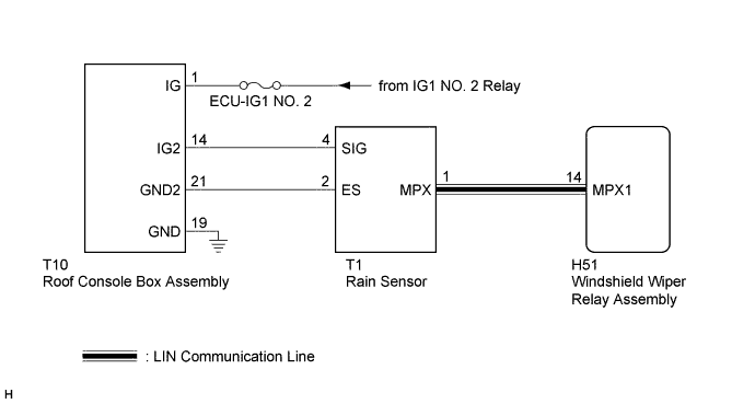
The windshield wiper relay assembly receives a signal from the rain sensor to control the auto wiper system.
WIRING DIAGRAM
INSPECTION PROCEDURE
Note
Inspect the fuses for circuits related to this system before performing the following inspection procedure.
PROCEDURE
-
CHECK HARNESS AND CONNECTOR (WINDSHIELD WIPER RELAY ASSEMBLY - RAIN SENSOR)
-
Disconnect the H51 windshield wiper relay assembly connector.
-
Disconnect the T1 rain sensor connector.
-
Measure the resistance according to the value(s) in the table below.
Standard Resistance Tester Connection Condition Specified Condition H51-14 (MPX1) - T1-1 (MPX) Always Below 1 Ω T1-1 (MPX) - Body ground Always 10 kΩ or higher
NG 
REPAIR OR REPLACE HARNESS OR CONNECTOR
OK 
-
-
CHECK HARNESS AND CONNECTOR (ROOF CONSOLE BOX ASSEMBLY - IG CIRCUIT AND BODY GROUND)
-
Disconnect the T10 roof console box assembly.
-
Measure the voltage according to the value(s) in the table below.
Standard Voltage Tester Connection Condition Specified Condition T10-1 (IG) - T10-21 (GND2) Engine switch on (IG) 11 to 14 V
NG
REPAIR OR REPLACE HARNESS OR CONNECTOR
OK
-
-
CHECK HARNESS AND CONNECTOR (RAIN SENSOR - BATTERY AND BODY GROUND)
-
Measure the resistance according to the value(s) in the table below.
Standard Resistance Tester Connection Condition Specified Condition T1-2 (ES) - T10-21 (GND2) Always Below 1 Ω T1-4 (SIG) - T10-14 (IG2) Always Below 1 Ω
NG
REPAIR OR REPLACE HARNESS OR CONNECTOR
OK
-
-
INSPECT ROOF CONSOLE BOX ASSEMBLY
-
Reconnect the T10 roof console box assembly.
-
Measure the voltage according to the value(s) in the table below.
Standard Voltage Tester Connection Condition Specified Condition T1-4 (SIG) - T1-2 (ES) Engine switch on (IG) 11 to 14 V
NG
REPLACE ROOF CONSOLE BOX ASSEMBLY Click here
OK
-
-
INSPECT RAIN SENSOR
-
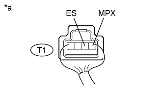
Text in Illustration *a Component with harness connected
(Rain Sensor)
Reconnect the T1 rain sensor connector.
-
Connect an oscilloscope to the rain sensor connector.
-
Check for pulses.
OK Tester Connection Condition Specified Condition T1-1 (MPX) - T1-2 (ES) Engine switch on (IG) Pulse generation
NG
REPLACE RAIN SENSOR Click here
OK 
PROCEED TO NEXT SUSPECTED AREA SHOWN IN PROBLEM SYMPTOMS TABLE Click here
-