OUTER REAR VIEW MIRROR INSTALLATION

Tech Tips
-
Use the same procedure for the LH side and RH side.
-
The following procedure is for the LH side.
-
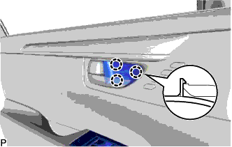
INSTALL OUTER REAR VIEW MIRROR ASSEMBLY
-
Engage the clamp to temporarily install the outer rear view mirror assembly.
-
Install the outer rear view mirror assembly with the 3 nuts.
- Torque:
- 5.5 N*m { 56 kgf*cm, 49 in.*lbf }
-
-
INSTALL OUTER MIRROR INSTALL HOLE COVER
-
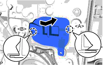
Engage the claw<A> as shown in the illustration.
-
Engage the claw<B> as shown in the illustration.
-
Install the outer mirror install hole cover with the screw.
-
w/o Memory:
-
Connect the connector.
-
-
-
INSTALL OUTER MIRROR PROTECTOR
-
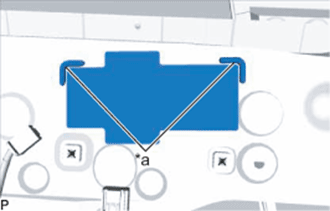
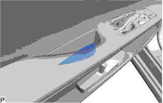
Text in Illustration *a Reference Point Install a new outer mirror protector while aligning it to the reference points on the front door panel.
-
-
INSTALL OUTER MIRROR CONTROL ECU ASSEMBLY (w/ Memory)
-
Install the outer mirror control ECU assembly with the 2 screws.
-
Connect the 2 connectors.
-
-
INSTALL FRONT DOOR INNER GLASS WEATHERSTRIP
-
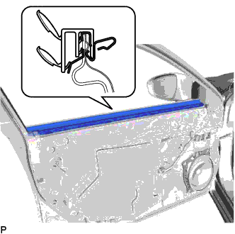
Install the front door inner glass weatherstrip.
-
-
INSTALL FRONT DOOR TRIM BOARD SUB-ASSEMBLY
-
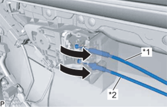
Text in Illustration *1 Front Door Inside Locking Cable Assembly *2 Front Door Lock Remote Control Cable Assembly Connect the front door lock remote control cable assembly and front door inside locking cable assembly.
-
w/ Memory:
-
Connect the connector.
-
-
w/ Illumination:
-
Connect the connector.
-
-
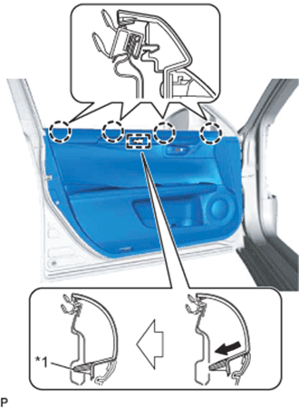
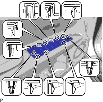
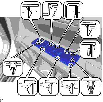
Text in Illustration *1 Reference Boss Engage the front door trim board sub-assembly with the 4 claws and reference boss as shown in the illustration.
-
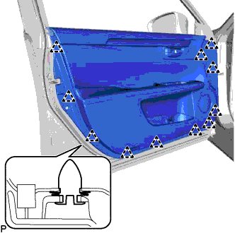
Engage the 11 clips to temporary install the front door trim board sub-assembly.
-
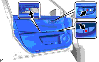
Install the 3 screws to install the front door trim board sub-assembly.
-
-
INSTALL FRONT DOOR NO. 1 STIFFENER CUSHION
-
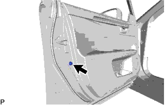
Install the front door No. 1 stiffener cushion with the screw.
-
-
INSTALL COURTESY LIGHT ASSEMBLY
-
Connect the connector.
-
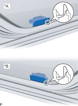
Text in Illustration *A for LH Side *B for RH Side Engage the claw to install the courtesy light assembly.
-
-
INSTALL DOOR PULL HANDLE COVER
-
Install the door pull handle cover.
-
-
INSTALL MULTIPLEX NETWORK MASTER SWITCH ASSEMBLY WITH FRONT DOOR ARMREST BASE PANEL (for Driver Side)
-
Connect each connector.
-
Engage the 2 guides, 2 clips and 6 claws, to install the multiplex network master switch assembly with front door armrest base panel.
-
-
INSTALL POWER WINDOW REGULATOR SWITCH ASSEMBLY WITH FRONT DOOR ARMREST BASE PANEL (for Front Passenger Side)
-
Connect each connector.
-
Engage the 2 guides, 2 clips and 6 claws, to install the power window regulator switch assembly with front door armrest base panel.
-
-
INSTALL FRONT DOOR INSIDE HANDLE BEZEL PLUG
-
Engage the 3 claws to install the front door inside handle bezel plug.
-
-
CONNECT CABLE TO NEGATIVE BATTERY TERMINAL
Note
When disconnecting the cable, some systems need to be initialized after the cable is reconnected Click here.
-
INITIALIZE POWER WINDOW CONTROL SYSTEM
-
INSPECT POWER WINDOW OPERATION