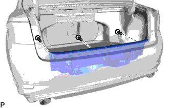
LUGGAGE COMPARTMENT DOOR ADJUSTMENT

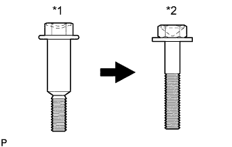
| *1 | Centering Bolt |
| *2 | Standard Bolt |
Tech Tips
-
Centering bolts are used to mount the door hinge to the door. The door cannot be adjusted with the centering bolts installed. Substitute the centering bolts with standard bolts when making adjustments.
-
Specified torque for standard bolts is shown in the standard bolt chart Click here.
-
REMOVE LUGGAGE LOCK CONTROL CABLE PLATE
-
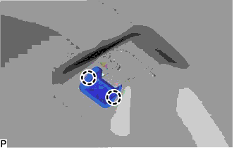
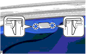
Disengage the 2 claws and remove the luggage lock control cable plate.
-
-
REMOVE LUGGAGE COMPARTMENT DOOR INSIDE HANDLE
-
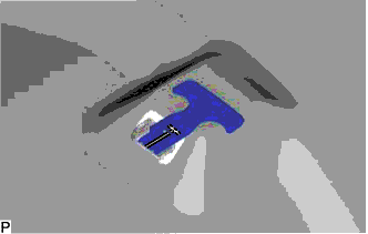
Remove the luggage compartment door inside handle from the luggage door lock control cable sub-assembly.
-
-
REMOVE LUGGAGE COMPARTMENT DOOR ASSIST GRIP
-
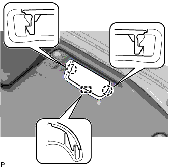
Disengage the 2 claws and guide and open the cover.
-
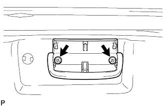
Remove the 2 screws and luggage compartment door assist grip.
-
-
REMOVE LUGGAGE COMPARTMENT DOOR COVER
-
w/o Power Trunk Lid System:
-
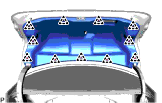
Using a clip remover, remove the 11 clips and luggage compartment door cover.
-
-
w/ Power Trunk Lid System:
-
Using a clip remover, remove the 11 clips.
-
Disengage the 2 claws and remove the luggage compartment door cover.
-
-
-
REMOVE LUGGAGE COMPARTMENT FLOOR MAT
-
Remove the luggage compartment floor mat.
-
-
REMOVE SPARE WHEEL COVER PAD LH
-
Remove the spare wheel cover pad LH.
-
-
REMOVE SPARE WHEEL COVER PAD RH
-
Remove the spare wheel cover pad RH.
-
-
REMOVE LUGGAGE HOLD BELT STRIKER ASSEMBLY
-
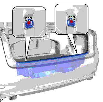
Remove the 2 bolts.
-
Disengage the 2 guides and remove the 2 luggage hold belt striker assemblies.
-
-
REMOVE REAR FLOOR FINISH PLATE
-
Using a clip remover, remove the 3 clips.
-
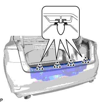
Disengage the 4 clips and remove the rear floor finish plate.
-
-
ADJUST LUGGAGE COMPARTMENT DOOR
-
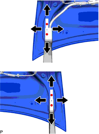
Loosen the 4 door side hinge bolts to adjust the door horizontally and vertically.
- Torque:
- 7.0 N*m { 71 kgf*cm, 62 in.*lbf }
-
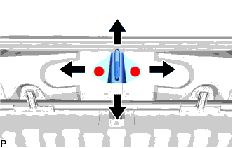
Using a T40 "TORX" socket wrench, slightly loosen the 2 striker mounting screws.
-
Using a brass bar and a hammer, hit the striker to adjust its position.
-
Using a T40 "TORX" socket wrench, tighten the 2 striker mounting screws after adjustment.
- Torque:
- 23 N*m { 235 kgf*cm, 17 ft.*lbf }
-
-
INSTALL REAR FLOOR FINISH PLATE
-
Engage the 4 clips and install the rear floor finish plate.
-
Install the 3 clips.
-
-
INSTALL LUGGAGE HOLD BELT STRIKER ASSEMBLY
-
Engage the 2 guides.
-
Install the 2 luggage hold belt striker assemblies with the 2 bolts.
-
-
INSTALL SPARE WHEEL COVER PAD RH
-
Install the spare wheel cover pad RH.
-
-
INSTALL SPARE WHEEL COVER PAD LH
-
Install the No. 2 spare wheel cover pad LH.
-
-
INSTALL LUGGAGE COMPARTMENT FLOOR MAT
-
Install the luggage compartment floor mat.
-
-
INSTALL LUGGAGE COMPARTMENT DOOR COVER
-
w/o Power Trunk Lid System:
-
Install the luggage compartment door cover with the 11 clips.
-
-
w/ Power Trunk Lid System:
-
Engage the 2 claws.
-
Install the luggage compartment door cover with the 11 clips.
-
-
-
INSTALL LUGGAGE COMPARTMENT DOOR ASSIST GRIP
-
Install the luggage compartment door assist grip with the 2 screws.
-
Engage the guide and 2 claws and close the cover.
-
-
INSTALL LUGGAGE COMPARTMENT DOOR INSIDE HANDLE
-
Install the luggage compartment door inside handle to the luggage door lock control cable sub-assembly.
-
-
INSTALL LUGGAGE LOCK CONTROL CABLE PLATE
-
Engage the 2 claws to install the luggage lock control cable plate.
-
-
INSPECT LUGGAGE COMPARTMENT DOOR
-
Check that the clearance measurements of areas "a" through "d" are within each standard range.
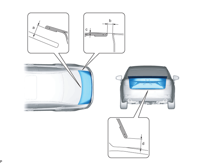
Standard Clearance Area Measurement Area Measurement a 7.0 mm (0.276 in.) b 2.3 to 5.3 mm (0.0906 to 0.209 in.) c -1.5 to 1.5 mm (-0.0591 to 0.0591 in.) d 4.0 to 8.0 mm (0.157 to 0.315 in.)
-