SLIDING ROOF HOUSING (for Glass Roof) INSTALLATION

-
TEMPORARILY TIGHTEN SLIDING ROOF HOUSING PANEL
-
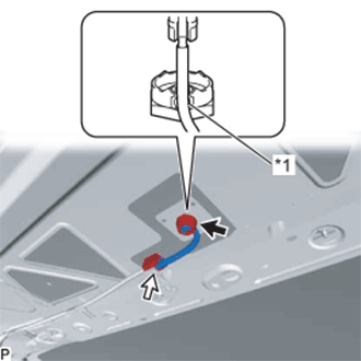
Pass a string under the back window outside moulding as shown in the illustration.
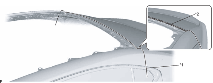
Text in Illustration *1 String *2 Back Window Outside Moulding -
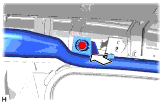
Temporarily install the sliding roof housing panel with the 20 nuts.
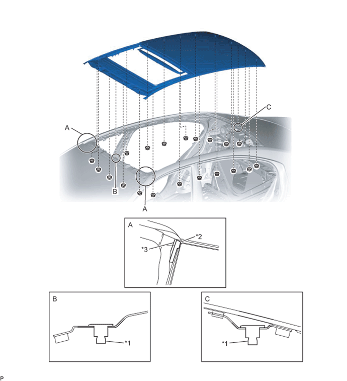
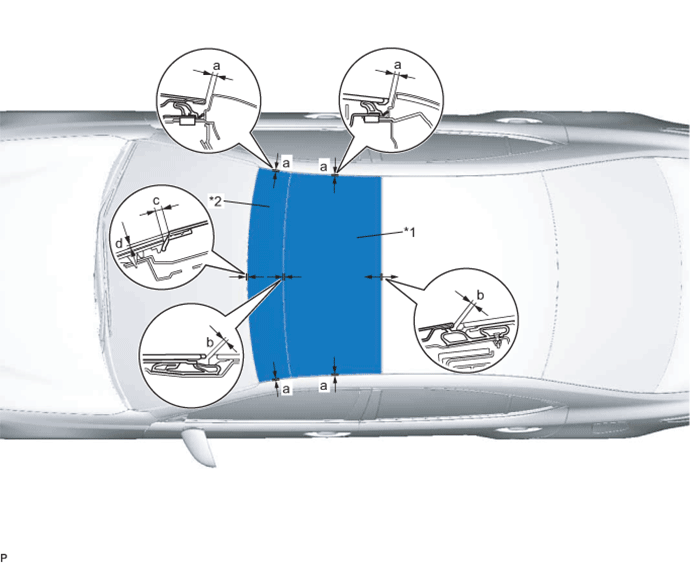
Text in Illustration *1 Alignment Pin *2 Side Weatherstrip *3 Body Line - - Note
-
When installing the panel to the vehicle, first install the panel center front and center rear alignment pins to the vehicle front and rear alignment pin installation points, as shown in the illustration.
-
Front part of side weatherstrip should install behind the line.
-
When installing the panel, be careful not to damage the vehicle.
-
-
Check that the alignment pins and bolts are firmly installed.
Note
When the alignment pins and bolts are not firmly installed, water leaks and malfunctions will occur.
-
-
ADJUST SLIDING ROOF HOUSING PANEL
-
Change the position of the sliding roof housing panel so that the measurements are within the standard values shown in the illustration.
Tech Tips
The sliding roof housing panel does not have adjusting screws.
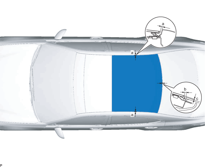
Standard Area Measurement a 2.0 to 6.0 mm (0.0787 to 0.236 in.) b 4.6 mm (0.181 in.) c 0.0 to 4.0 mm (0.0 to 0.157 in.) -
Fully tighten the 20 nuts to install the sliding roof housing panel.
- Torque:
- 5.5 N*m { 56 kgf*cm, 49 in.*lbf }
-
Apply soapy water to the back window outside moulding.
-
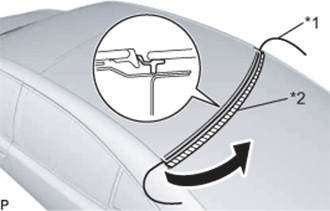
Text in Illustration *1 String *2 Back Window Outside Moulding Slowly pull out the string to install the back window outside moulding to the correct position.
-
-
INSTALL SLIDING ROOF HOUSING ASSEMBLY
-
Install the sliding roof housing assembly with the 10 nuts.
- Torque:
- 6.3 N*m { 64 kgf*cm, 56 in.*lbf }
-
Using a T25 "TORX" socket wrench, install the 6 screws.
- Torque:
- 5.0 N*m { 51 kgf*cm, 44 in.*lbf }
-
-
INSTALL CENTER SLIDING ROOF HOUSING MOUNTING BRACKET LH
-
Install the center sliding roof housing mounting bracket LH with the 3 bolts and 2 nuts.
- Torque:
- Bolt
- 8.0 N*m { 82 kgf*cm, 71 in.*lbf }
- Nut
- 5.5 N*m { 56 kgf*cm, 49 in.*lbf }
-
-
INSTALL CENTER SLIDING ROOF HOUSING MOUNTING BRACKET RH
Tech Tips
Use the same procedure as for the LH side.
-
INSTALL FRONT SLIDING ROOF HOUSING MOUNTING BRACKET LH
-
Install the front sliding roof housing mounting bracket LH with the 2 bolts and 2 nuts.
- Torque:
- Bolt
- 8.0 N*m { 82 kgf*cm, 71 in.*lbf }
- Nut
- 5.5 N*m { 56 kgf*cm, 49 in.*lbf }
-
-
INSTALL FRONT SLIDING ROOF HOUSING MOUNTING BRACKET RH
Tech Tips
Use the same procedure as for the LH side.
-
INSTALL CURTAIN SHIELD AIRBAG ASSEMBLY LH
-
Check that the engine switch is off.
-
Check that the cable is disconnected from the negative (-) battery terminal.
CAUTION:
Wait at least 90 seconds after disconnecting the cable from the negative (-) battery terminal to disable the SRS system.
-
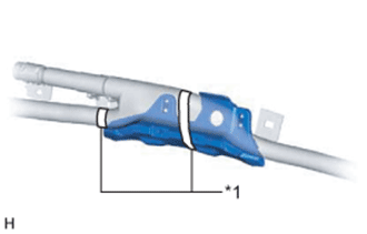
Text in Illustration *1 New Tape Apply 2 new tapes to install the rear No. 2 side rail spacer to the curtain shield airbag assembly as shown in the illustration.
-
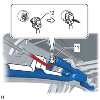
Text in Illustration *1 Airbag Connector *2 Airbag Connector Lock Connect the airbag connector.
Note
When connecting any airbag connector, take care not to damage the airbag wire harness.
-
Push in the airbag connector lock to install the curtain shield airbag connector.
-
Engage the 2 clamps and 4 hooks to temporarily install the curtain shield airbag assembly.
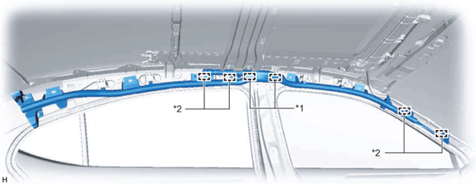
Text in Illustration *1 Clamp *2 Hook Note
-
When installing the curtain shield airbag assembly, have assistants hold it to prevent it from bending.
-
Do not twist the curtain shield airbag assembly when installing it.
-
-
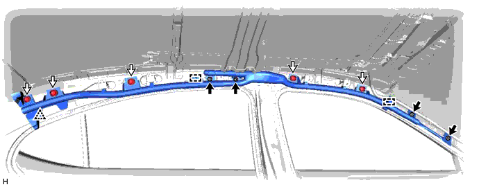
Engage the 2 clamps and clip.
-
Install 5 new clips.
Text in Illustration 
New Bolt 
New Clip -
Install 4 new bolts.
- Torque:
- 11 N*m { 110 kgf*cm, 8 ft.*lbf }
-
Push in 5 new pins to each clip.
Note
Make sure that the pins of the clips are pushed in firmly.
-
-
INSTALL CURTAIN SHIELD AIRBAG ASSEMBLY RH
Tech Tips
Use the same procedure as for the LH side.
-
INSTALL TELEPHONE ANTENNA ASSEMBLY (w/ Antenna)
-
Engage the 2 claws to the vehicle body to temporarily install the telephone antenna assembly.
-
Text in Illustration *1 Cutout Place the antenna cord in the cutout of the antenna nut.
-
Install the telephone antenna assembly with the antenna nut.
- Torque:
- 4.5 N*m { 46 kgf*cm, 40 in.*lbf }
-
Connect the connector.
-
-
INSTALL ROOF HEADLINING ASSEMBLY
-
TEMPORARILY TIGHTEN SLIDING ROOF PANEL SUB-ASSEMBLY
-
Using a T20 "TORX" socket wrench, temporarily install the sliding roof panel sub-assembly with the 6 screws.
-
-
TEMPORARILY TIGHTEN SLIDING ROOF GLASS SUB-ASSEMBLY
-
Using a T25 "TORX" socket wrench, temporarily install the sliding roof glass sub-assembly with the 6 screws.
-
-
ADJUST SLIDING ROOF GLASS SUB-ASSEMBLY AND SLIDING ROOF PANEL SUB-ASSEMBLY
-
Adjust the sliding roof glass sub-assembly.
Text in Illustration *1 Sliding Roof Glass Sub-assembly *2 Sliding Roof Panel Sub-assembly
-
Adjust the position of the sliding roof glass sub-assembly so that the measurements are within the standard values shown in the illustration.
Standard Area Measurement a 2.0 to 6.0 mm (0.0787 to 0.236 in.) b 3.0 mm (0.118 in.) -
After adjusting the sliding roof glass sub-assembly, using a T25 "TORX" socket wrench, fully tighten the 6 screws to install the sliding roof glass sub-assembly.
- Torque:
- 5.0 N*m { 51 kgf*cm, 44 in.*lbf }
-
-
Adjust the sliding roof panel sub-assembly.
-
Fully open the sliding roof glass sub-assembly.
-
Adjust the position of the sliding roof panel sub-assembly so that the measurements are within the standard values shown in the following table.
Standard Area Measurement a 2.0 to 6.0 mm (0.0787 to 0.236 in.) b 3.0 mm (0.118 in.) c 5.0 mm (0.204 in.) d 0.0 to 4.0 mm (0.0 to 0.157 in.) -
After adjusting the sliding roof panel sub-assembly, using a T20 "TORX" socket wrench, fully tighten the 6 screws to install the sliding roof panel sub-assembly.
- Torque:
- 2.8 N*m { 29 kgf*cm, 25 in.*lbf }
-
-
-
INSTALL SLIDING ROOF SIDE GARNISH LH
-
Install the sliding roof side garnish LH.
-
-
INSTALL SLIDING ROOF SIDE GARNISH RH
Tech Tips
Use the same procedure as for the LH side.
-
INSPECT FOR WATER LEAK
-
After adjusting the sliding roof glass sub-assembly, check for water leakage into the vehicle interior.
-
If there are any leaks, readjust the sliding roof glass sub-assembly.
-
-
RESET SLIDING ROOF DRIVE GEAR SUB-ASSEMBLY
-
CHECK SLIDING ROOF SYSTEM