PRE-CRASH SAFETY SYSTEM Pre-crash Safety System Cancel Switch Circuit
DESCRIPTION
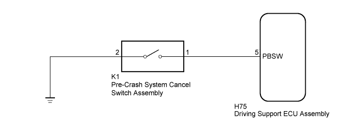
The driving support ECU assembly receives a pre-crash system on/off signal from the pre-crash system cancel switch assembly.
WIRING DIAGRAM
INSPECTION PROCEDURE
PROCEDURE
-
INSPECT PRE-CRASH SYSTEM CANCEL SWITCH ASSEMBLY
-
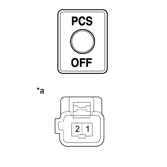
Text in Illustration *a Component without harness connected
(Pre-crash system cancel switch assembly)
Remove the pre-crash system cancel switch assembly Click here.
-
Measure the resistance according to the value(s) in the table below.
Standard Resistance Tester Connection Condition Specified Condition 1 - 2 Pressed Below 1 Ω Not pressed 10 kΩ or higher
NG 
REPLACE PRE-CRASH SYSTEM CANCEL SWITCH ASSEMBLY Click here
OK 
-
-
CHECK HARNESS AND CONNECTOR (PRE-CRASH SYSTEM CANCEL SWITCH ASSEMBLY - DRIVING SUPPORT ECU ASSEMBLY)
-
Disconnect the K1 pre-crash system cancel switch assembly connector.
-
Disconnect the H75 driving support ECU assembly connector.
-
Measure the resistance according to the value(s) in the table below.
Standard Resistance Tester Connection Condition Specified Condition K1-1 - H75-5 (PBSW) Always Below 1 Ω K1-1 or H75-5 (PBSW) - Body ground Always 10 kΩ or higher
NG
REPAIR OR REPLACE HARNESS OR CONNECTOR
OK
-
-
CHECK HARNESS AND CONNECTOR (PRE-CRASH SYSTEM CANCEL SWITCH ASSEMBLY - BODY GROUND)
-
Disconnect the K1 pre-crash system cancel switch assembly connector.
-
Measure the resistance according to the value(s) in the table below.
Standard Resistance Tester Connection Condition Specified Condition K1-2 - Body ground Always Below 1 Ω
NG
REPAIR OR REPLACE HARNESS OR CONNECTOR
OK 
REPLACE DRIVING SUPPORT ECU ASSEMBLY Click here
-