SPIRAL CABLE INSTALLATION

-
INSTALL SPIRAL CABLE WITH SENSOR SUB-ASSEMBLY
Note
-
Do not replace the spiral cable with sensor sub-assembly with the battery connected and the engine switch on (IG).
-
Do not rotate the spiral cable with sensor sub-assembly without the steering wheel with the battery connected and the engine switch on (IG).
-
Ensure that the steering wheel is installed and aligned straight when inspecting the steering sensor.
-
Check that the engine switch is off.
-
Check that the cable is disconnected from the negative (-) battery terminal.
CAUTION:
Wait at least 90 seconds after disconnecting the cable from the negative (-) battery terminal to disable the SRS system.
-
Check that the front wheels are facing straight ahead.
-
Set the turn signal switch to the neutral position.
Note
If it is not in the neutral position, the turn signal switch pin may snap.
-
Engage the 3 claws to install the spiral cable with sensor sub-assembly.
-
Connect each connectors.
-
-
INSTALL UPPER STEERING COLUMN COVER
-
Engage the 2 claws to install the upper steering column cover.
-
Engage the 4 clips and 2 guides to the upper steering column cover.
-
-
INSTALL LOWER STEERING COLUMN COVER
for Manual Tilt and Manual Telescopic Steering Column: Click here
for Power Tilt and Power Telescopic Steering Column: Click here
-
ALIGN FRONT WHEELS FACING STRAIGHT AHEAD
-
INSPECT AND ADJUST SPIRAL CABLE WITH SENSOR SUB-ASSEMBLY
Note
Do not adjust the spiral cable with sensor sub-assembly with the battery connected and the engine switch on (IG).
-
Check that the engine switch is off.
-
Check that the cable is disconnected from the negative (-) battery terminal.
CAUTION:
Wait at least 90 seconds after disconnecting the cable from the negative (-) battery terminal to disable the SRS system.
-
Check if the spiral cable with sensor sub-assembly is centered.
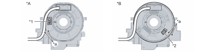
Text in Illustration *A w/o Steering Heater *B w/ Steering Heater *1 Colored Part *2 Flat Cable *a Alignment Mark - - Tech Tips
When the spiral cable with sensor sub-assembly is centered, the alignment marks are aligned and the colored part or flat cable shown in the illustration is visible.
-
If the spiral cable with sensor sub-assembly is not centered, center it.
Note
-
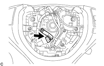
When rotating the spiral cable with sensor sub-assembly, make sure to push on the interlock indicated in the illustration to release the interlock mechanism.
-
Do not turn the spiral cable with sensor sub-assembly using the airbag wire harness.
-
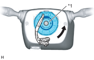
Text in Illustration *1 Interlock While pushing on the interlock indicated in the illustration, rotate the spiral cable with sensor sub-assembly counterclockwise slowly by hand until it stops.
-
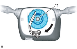
Text in Illustration *1 Interlock While pushing on the interlock indicated in the illustration, rotate the spiral cable with sensor sub-assembly clockwise approximately 2.5 turns to the position where the colored part or flat cable is visible.
Tech Tips
The spiral cable with sensor sub-assembly will rotate approximately 2.5 turns to both the left and right from the center.
-
-
-
INSTALL STEERING WHEEL ASSEMBLY
-
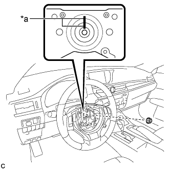
Text in Illustration *a Matchmark Install the steering wheel assembly aligning the matchmarks on the steering wheel assembly and steering main shaft.
-
Install the steering wheel assembly set nut.
- Torque:
- 50 N*m { 510 kgf*cm, 37 ft.*lbf }
-
w/ Steering Heater:
-
Connect the connector.
-
-
Connect the connectors to the spiral cable sub-assembly.
-
-
INSTALL STEERING WHEEL CENTER POINT
-
INSTALL HORN BUTTON ASSEMBLY
-
Check that the engine switch is off.
-
Check that the cable is disconnected from the negative (-) battery terminal.
CAUTION:
Wait at least 90 seconds after disconnecting the cable from the negative (-) battery terminal to disable the SRS system.
-
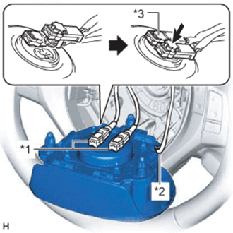
Text in Illustration *1 Airbag Connector *2 Horn Connector *3 Airbag Connector Lock Connect the 2 airbag connectors to the horn button assembly.
Note
-
When connecting any airbag connector, take care not to damage the airbag wire harness.
-
Be sure to only connect the connectors to each corresponding color.
-
-
Push in the 2 airbag connector locks to install the 2 airbag connectors.
-
Connect the horn connector to the horn button assembly.
-
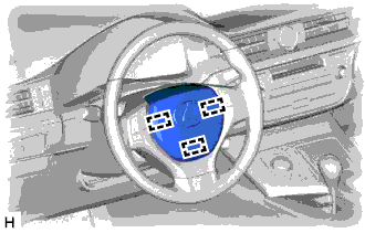
Push the horn button assembly to engage the 3 pins carefully.
Note
-
Make sure that the pins are securely inserted into the steering holes.
-
Make sure to engage the 2 upper pins first.
-
Make sure that the horn button assembly is securely installed.
-
-
-
INSTALL LOWER NO. 3 STEERING WHEEL COVER
-
Engage the claw and guide to install the lower No. 3 steering wheel cover.
-
-
INSTALL LOWER NO. 2 STEERING WHEEL COVER
-
Engage the claw and guide to install the lower No. 2 steering wheel cover.
-
-
CONNECT CABLE TO NEGATIVE BATTERY TERMINAL (for Power Tilt and Power Telescopic Steering Column)
Note
-
When disconnecting the cable, some systems need to be initialized after the cable is reconnected Click here.
-
Connect the cable to the negative (-) battery terminal with the front wheels facing straight ahead.
-
Reset the auto tilt away function setting to the previous condition by changing the customize parameter Click here.
-
-
CONNECT CABLE TO NEGATIVE BATTERY TERMINAL (for Manual Tilt and Manual Telescopic Steering Column)
Note
When disconnecting the cable, some systems need to be initialized after the cable is reconnected Click here.
-
INSPECT HORN BUTTON ASSEMBLY
-
Make sure that the horn sounds.
If the horn does not sound, inspect the horn system Click here.
-
-
PERFORM DIAGNOSTIC SYSTEM CHECK
-
INSPECT SRS WARNING LIGHT
-
ADJUST PARKING ASSIST MONITOR SYSTEM (w/ Parking Assist Monitor System)
w/o Parallel Parking Assist Function: Click here
w/ Parallel Parking Assist Function: Click here