LIGHTING SYSTEM Footwell Light Circuit
DESCRIPTION
The main body ECU (multiplex network body ECU) controls the footwell lights.
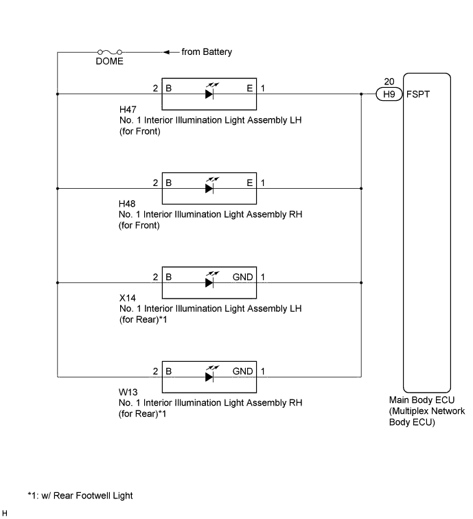
WIRING DIAGRAM
INSPECTION PROCEDURE
Note
If the main body ECU (multiplex network body ECU) is replaced, refer to Service Bulletin.
PROCEDURE
-
PERFORM ACTIVE TEST USING GTS
-
Connect the GTS to the DLC3.
-
Turn the engine switch on (IG).
-
Turn the GTS on.
-
Enter the following menus: Body Electrical / Main Body / Active Test.
-
Check that the footwell lights come on.
Main Body Tester Display Test Part Control Range Diagnostic Note Fr Foot Light Footwell lights ON/OFF Engine switch is turned off just before performing the Active Test. OK Footwell lights come on.
NG 
CHECK HARNESS AND CONNECTOR (DOME FUSE - NO. 1 INTERIOR ILLUMINATION LIGHT ASSEMBLY) Click here
OK 
PROCEED TO NEXT SUSPECTED AREA SHOWN IN PROBLEM SYMPTOMS TABLE Click here
-
-
CHECK HARNESS AND CONNECTOR (DOME FUSE - NO. 1 INTERIOR ILLUMINATION LIGHT ASSEMBLY)
-
Disconnect the H47 No. 1 interior illumination light assembly LH connector.
-
Disconnect the H48 No. 1 interior illumination light assembly RH connector.
-
Disconnect the X14 No. 1 interior illumination light assembly LH connector.*1
-
Disconnect the W13 No. 1 interior illumination light assembly RH connector.*1
-
Measure the voltage according to the value(s) in the table below.
Standard Voltage Tester Connection Condition Specified Condition H47-2 (B) - Body ground Engine switch off 11 to 14 V H48-2 (B) - Body ground Engine switch off 11 to 14 V X14-2 (B) - Body ground*1 Engine switch off 11 to 14 V W13-2 (B) - Body ground*1 Engine switch off 11 to 14 V
-
*1: w/ Rear Footwell Light
-
NG 
REPAIR OR REPLACE HARNESS OR CONNECTOR
OK 
-
-
CHECK HARNESS AND CONNECTOR (NO. 1 INTERIOR ILLUMINATION LIGHT ASSEMBLY - MAIN BODY ECU (MULTIPLEX NETWORK BODY ECU))
-
Disconnect the H9 main body ECU (multiplex network body ECU) connector.
-
Measure the resistance according to the value(s) in the table below.
Standard Resistance Tester Connection Condition Specified Condition H47-1 (E) - H9-20 (FSPT) Always Below 1 Ω H48-1 (E) - H9-20 (FSPT) Always Below 1 Ω X14-1 (GND) - H9-20 (FSPT) Always Below 1 Ω W13-1 (GND) - H9-20 (FSPT) Always Below 1 Ω H47-1 (E) - Body ground Always 10 kΩ or higher
NG
REPAIR OR REPLACE HARNESS OR CONNECTOR
OK
REPLACE MAIN BODY ECU (MULTIPLEX NETWORK BODY ECU) Click here
-