LIGHTING SYSTEM Interior Light Power Source Circuit
DESCRIPTION
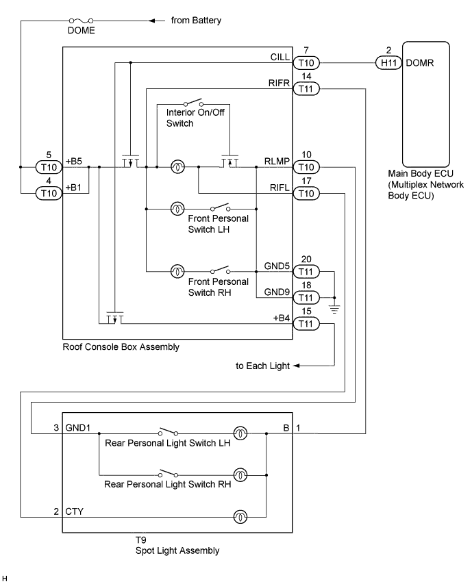
The main body ECU (multiplex network body ECU) controls the solid-state relay, that is built into the roof console box assembly, to supply power to the interior lights.
WIRING DIAGRAM
INSPECTION PROCEDURE
Note
Inspect the fuses for circuits related to this system before performing the following inspection procedure.
PROCEDURE
-
INSPECT ROOF CONSOLE BOX ASSEMBLY
-
Remove the roof console box assembly Click here.
-
Inspect the roof console box assembly Click here.
OK Roof console box assembly is normal.
NG 
REPLACE ROOF CONSOLE BOX ASSEMBLY Click here
OK 
-
-
CHECK HARNESS AND CONNECTOR (DOME FUSE - ROOF CONSOLE BOX ASSEMBLY)
-
Measure the voltage according to the value(s) in the table below.
Standard Voltage Tester Connection Condition Specified Condition T10-4 (+B1) - Body ground Engine switch off 11 to 14 V T10-5 (+B5) - Body ground Engine switch off 11 to 14 V
NG
REPAIR OR REPLACE HARNESS OR CONNECTOR
OK
-
-
CHECK HARNESS AND CONNECTOR (ROOF CONSOLE BOX ASSEMBLY - MAIN BODY ECU (MULTIPLEX NETWORK BODY ECU))
-
Disconnect the H11 main body ECU (multiplex network body ECU) connector.
-
Measure the resistance according to the value(s) in the table below.
Standard Resistance Tester Connection Condition Specified Condition T10-7 (CILL) - H11-2 (DOMR) Always Below 1 Ω T10-7 (CILL) - Body ground Always 10 kΩ or higher
NG
REPAIR OR REPLACE HARNESS OR CONNECTOR
OK 
PROCEED TO NEXT SUSPECTED AREA SHOWN IN PROBLEM SYMPTOMS TABLE Click here
-