BLOCKING SYSTEM, Diagnostic DTC:B1586

| DTC Code | DTC Name |
|---|---|
| B1586 | Open in Immobiliser Communication Circuit |
DESCRIPTION
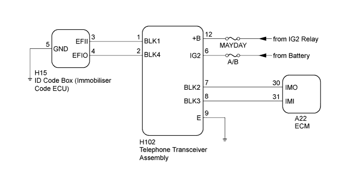
When the communication line (EFIO - BLK4) between the ID code box (immobiliser code ECU) and telephone transceiver assembly is open, the telephone transceiver assembly stores DTC B1586.
| DTC Code | DTC Detection Condition | Trouble Area |
|---|---|---|
| B1586 | The communication line (EFIO - BLK4) between the ID code box (immobiliser code ECU) and telephone transceiver assembly is open. |
|
WIRING DIAGRAM
INSPECTION PROCEDURE
Note
-
Before troubleshooting for this DTC, make sure no immobiliser system DTCs are present. If present, troubleshoot the immobiliser system DTCs first.
-
Inspect the fuses for circuits related to this system before performing the following inspection procedure.
-
When replacing the telephone transceiver assembly or ID code box (immobiliser code ECU), refer to the Service Bulletin.
-
When the telephone transceiver assembly is replaced, it is necessary to set the contract mode.
PROCEDURE
-
CHECK DTC OUTPUT
-
Clear the DTCs Click here.
-
Turn the engine switch off.
-
Turn the engine switch on (IG).
-
After 6 seconds have elapsed, check for DTCs.
Result Result Proceed to DTC is not output. A Only DTC B1586 is output. B DTC B1586 and other DTCs are output. C
B 
CHECK CONNECTION OF CONNECTOR Click here
C 
GO TO DIAGNOSTIC TROUBLE CODE CHART Click here
A 
USE SIMULATION METHOD TO CHECK Click here
-
-
CHECK CONNECTION OF CONNECTOR
-
Turn the engine switch off.
-
Check that the connectors are properly connected to the telephone transceiver assembly and ID code box (immobiliser code ECU).
OK Connectors are properly connected.
NG
CONNECT CONNECTOR CORRECTLY
OK 
-
-
CHECK HARNESS AND CONNECTOR (TELEPHONE TRANSCEIVER ASSEMBLY - ID CODE BOX (IMMOBILISER CODE ECU))
-
Disconnect the H102 telephone transceiver assembly connector.
-
Disconnect the H15 ID code box (immobiliser code ECU) connector.
-
Measure the resistance according to the value(s) in the table below.
Standard Resistance Tester Connection Condition Specified Condition H102-2 (BLK4) - H15-4 (EFIO) Always Below 1 Ω
NG
REPAIR OR REPLACE HARNESS OR CONNECTOR
OK
-
-
CHECK ID CODE BOX (IMMOBILISER CODE ECU) (OUTPUT)
-
Reconnect the H102 telephone transceiver assembly connector.
-
Reconnect the H15 ID code box (immobiliser code ECU) connector.
-
Using an oscilloscope, check the waveform.
Note
The waveform shown in the illustration is an example for reference only. Noise, chattering, etc. are not shown.
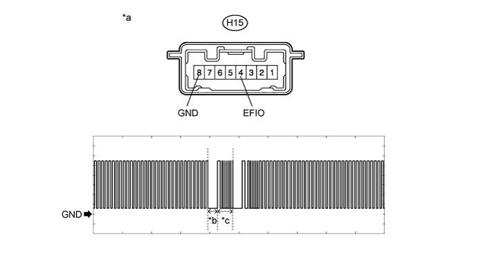
Text in Illustration *a Component with harness connected
(ID Code Box (Immobiliser Code ECU))
*b Approximately 160 ms *c Approximately 270 ms - - Measurement Condition Item Content Tester Connection H15-4 (EFIO) - H15-5 (GND) Tool Setting 2 V/DIV., 500 ms./DIV. Condition Within 3 seconds of engine start or within 3 seconds of engine switch turned on (IG) after battery cable disconnected and reconnected OK The waveform is output normally (refer to illustration).
NG
CHECK HARNESS AND CONNECTOR (TELEPHONE TRANSCEIVER ASSEMBLY - BATTERY AND BODY GROUND) Click here
OK
REPLACE TELEPHONE TRANSCEIVER ASSEMBLY
-
-
CHECK HARNESS AND CONNECTOR (TELEPHONE TRANSCEIVER ASSEMBLY - BATTERY AND BODY GROUND)
-
Disconnect the H102 telephone transceiver assembly connector.
-
Measure the resistance and voltage according to the value(s) in the table below.
Standard Voltage Tester Connection Condition Specified Condition H102-12 (+B) - Body ground Always 11 to 14 V H102-6 (IG2) - Body ground Engine switch off Below 1 V H102-6 (IG2) - Body ground Engine switch on (IG) 11 to 14 V Standard Resistance Tester Connection Condition Specified Condition H102-9 (E) - Body ground Always Below 1 Ω
NG
REPAIR OR REPLACE HARNESS OR CONNECTOR
OK
-
-
REPLACE ID CODE BOX (IMMOBILISER CODE ECU)
-
Temporarily replace the ID code box (immobiliser code ECU) with a new one.
Tech Tips
Refer to the Service Bulletin.
NEXT
-
-
PERFORM REGISTRATION
-
Perform the registration.
Tech Tips
Refer to the Service Bulletin.
NEXT
-
-
CHECK DTC OUTPUT
-
Clear the DTCs Click here.
-
Turn the engine switch off.
-
Turn the engine switch on (IG).
-
After 6 seconds have elapsed, check for DTCs.
OK DTC B1586 is not output.
NG
REPLACE TELEPHONE TRANSCEIVER ASSEMBLY
OK
END (ID CODE BOX (IMMOBILISER CODE ECU) WAS DEFECTIVE)
-