BLOCKING SYSTEM, Diagnostic DTC:B15C0, B15C1

| DTC Code | DTC Name |
|---|---|
| B15C0 | Short in GPS Antenna |
| B15C1 | Open in GPS Antenna |
DESCRIPTION
These DTCs are stored when a malfunction occurs in the instrument panel integration antenna assembly (GPS antenna) circuit.
| DTC No. | DTC Detection Condition | Trouble Area |
|---|---|---|
| B15C0 | There is a short circuit in the instrument panel integration antenna assembly between the telephone transceiver assembly and instrument panel integration antenna assembly (GPS antenna), or at the points where it connects to the telephone transceiver assembly and instrument panel integration antenna assembly. |
|
| B15C1 | There is an open circuit in the instrument panel integration antenna assembly between the telephone transceiver assembly and instrument panel integration antenna assembly (GPS antenna), or at the points where it connects to the telephone transceiver assembly and instrument panel integration antenna assembly. |
INSPECTION PROCEDURE
Note
-
When replacing the telephone transceiver assembly or instrument panel integration antenna assembly, refer to the Service Bulletin.
-
When the telephone transceiver assembly is replaced, it is necessary to set the contract mode.
PROCEDURE
-
CHECK CONNECTION OF CONNECTOR
-
Turn the engine switch off.
-
Check that the connectors are properly connected to the telephone transceiver assembly and instrument panel integration antenna assembly (GPS antenna).
OK Connectors are properly connected.
NG 
CONNECT CONNECTOR CORRECTLY
OK 
-
-
CLEAR DTC
-
Clear the DTCs Click here.
NEXT
-
-
CHECK DTC OUTPUT
-
Check for DTCs Click here.
OK DTC B15C0 and B15C1 are not output.
NG 
CHECK CONNECTOR CONDITION Click here
OK 
END
-
-
CHECK CONNECTOR CONDITION
-
Turn the engine switch off.
-
Disconnect the instrument panel integration antenna assembly (GPS antenna) connector.
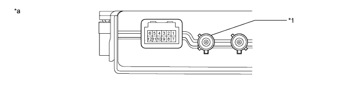
Text in Illustration *1 GPS antenna - - *a Component with harness connected
(Instrument Panel Integration Antenna Assembly)
- - -
Check that the connector pins are not bent.
OK Connector pins are not bent.
NG
REPAIR OR REPLACE INSTRUMENT PANEL INTEGRATION ANTENNA ASSEMBLY
OK
-
-
CHECK INSTRUMENT PANEL INTEGRATION ANTENNA ASSEMBLY
-
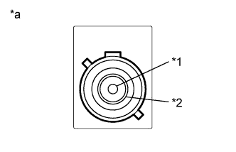
Text in Illustration *1 Core wire *2 Shield *a Component without harness connected
(Instrument Panel Integration Antenna Assembly (GPS Antenna))
Disconnect the instrument panel integration antenna assembly (GPS antenna) connector.
-
Measure the resistance according to the value(s) in the table below.
Standard Resistance Tester Connection Condition Specified Condition Core wire - Shield Always 50 to 500 Ω
NG
REPLACE INSTRUMENT PANEL INTEGRATION ANTENNA ASSEMBLY
OK
-
-
CLEAR DTC
-
Clear the DTCs Click here.
NEXT
-
-
CHECK DTC OUTPUT
-
Check for DTCs Click here.
OK DTC B15C0 and B15C1 is not output.
NG
REPLACE INSTRUMENT PANEL INTEGRATION ANTENNA ASSEMBLY Click here
OK
END
-
-
REPLACE INSTRUMENT PANEL INTEGRATION ANTENNA ASSEMBLY
-
Temporarily replace the instrument panel integration antenna assembly with a new or known good one.
Tech Tips
Refer to the Service Bulletin.
NEXT
-
-
CLEAR DTC
-
Clear the DTCs Click here.
NEXT
-
-
CHECK DTC OUTPUT
-
Check for DTCs Click here.
OK DTC B15C0 and B15C1 is not output.
NG
REPLACE TELEPHONE TRANSCEIVER ASSEMBLY
OK
END (INSTRUMENT PANEL INTEGRATION ANTENNA ASSEMBLY WAS DEFECTIVE)
-