CAN COMMUNICATION SYSTEM, Diagnostic DTC:U1002

| DTC Code | DTC Name |
|---|---|
| U1002 | Lost Communication with Gateway Module (Network Gateway ECU) |
DESCRIPTION
-
The network gateway ECU will store this DTC when no signals can be received from the ECUs that have been memorized as those that are connected to sub bus 2.
-
When the network gateway ECU receives a response signal from the ECUs connected to sub bus 2, the network gateway ECU recognizes and memorizes that the ECU is connected to sub bus 2. Based on this memorized data, the network gateway ECU monitors for malfunctions in the ECUs connected to sub bus 2 when communicating with those ECUs. If the network gateway ECU cannot receive response signals from the ECUs that have been memorized as those connected to sub bus 2, the network gateway ECU determines that a malfunction exists.
| DTC No. | DTC Detection Condition | Trouble Area |
|---|---|---|
| U1002 | The network gateway ECU cannot receive signals from all ECUs that have been memorized as those connected to sub bus 2. |
|
-
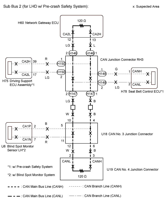
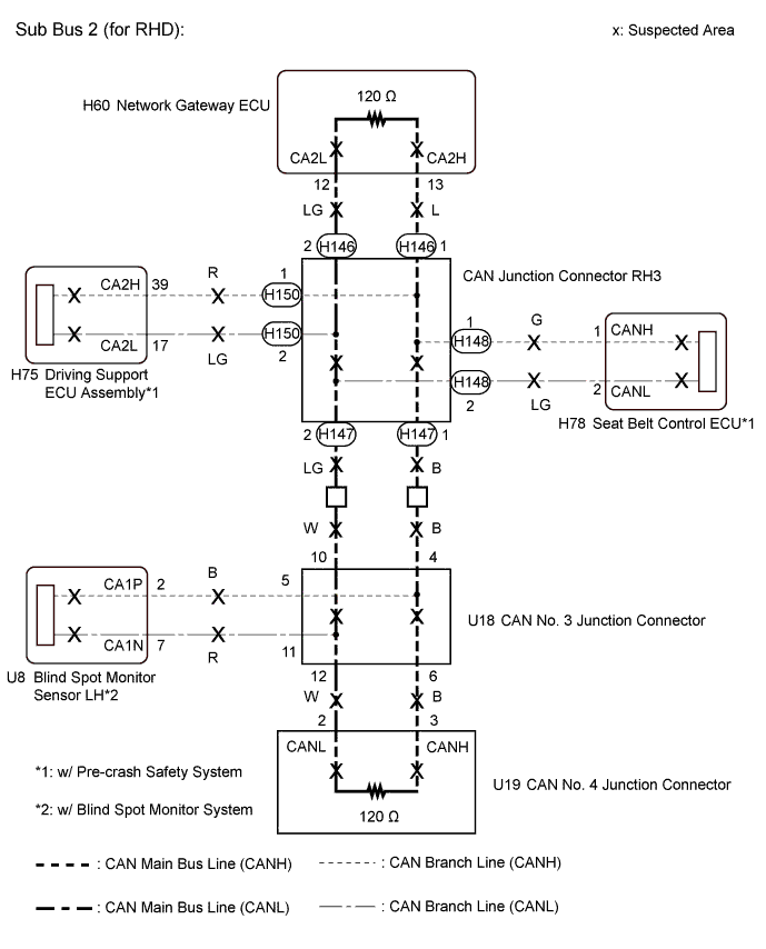
*1: w/ Pre-crash safety system
-
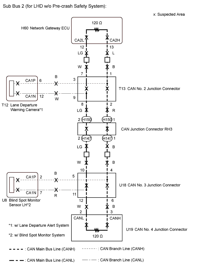
*2: for LHD w/o Pre-crash safety system
-
*3: for LHD w/ Lane departure alert system
-
*4: w/ Blind spot monitor system
Tech Tips
This diagnosis procedure is for when DTC U1002 is output by the network gateway ECU (GTS display: Gateway).
WIRING DIAGRAM
INSPECTION PROCEDURE
Note
-
Before measuring the resistance of the CAN bus, turn the engine switch off and leave the vehicle for 1 minute or more without operating the key, switches or opening or closing the doors. After that, disconnect the cable from the negative (-) battery terminal and leave the vehicle for 1 minute or more before measuring the resistance.
-
After turning the engine switch off, waiting time may be required before disconnecting the cable from the negative (-) battery terminal. Therefore, make sure to read the disconnecting the cable from the negative (-) battery terminal notices before proceeding with work Click here.
-
Because the order of diagnosis is important to allow correct diagnosis, make sure to begin troubleshooting using How to Proceed with Troubleshooting when CAN communication system related DTCs are output Click here.
-
After performing repairs, perform the DTC check procedure and confirm that the DTCs are not output again.
-
DTC check procedure: Turn the engine switch on (IG), turn the blind spot monitor main switch on, wait at least 20 seconds and then drive the vehicle at a speed of 5 km/h (3 mph) or more for 6.2 seconds or more.
-
After the repair, perform CAN bus check and check that all the ECUs and sensors connected to the CAN communication system are displayed Click here.
Tech Tips
-
Operating the engine switch, any other switches or a door triggers related ECU and sensor communication on the CAN. This communication will cause the resistance value to change.
-
Even after DTCs are cleared, if a DTC is stored again after driving the vehicle for a while, the malfunction may be occurring due to vibration of the vehicle. In such a case, wiggling the ECUs or wire harness while performing the inspection below may help determine the cause of the malfunction.
PROCEDURE
-
CHECK VEHICLE TYPE
-
Check vehicle type.
Result Result Proceed to for LHD (w/ Pre-crash safety system) A for LHD (w/o Pre-crash safety system) B for RHD C
B 
CHECK SUB BUS 2 Click here
C
CHECK SUB BUS 2 Click here
A 
-
-
CHECK SUB BUS 2
-
Disconnect the cable from the negative (-) battery terminal.
-
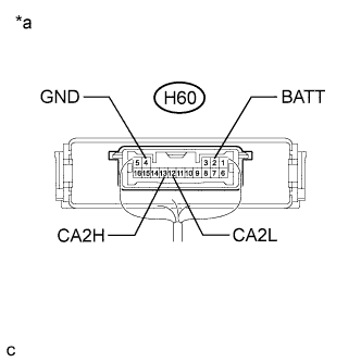
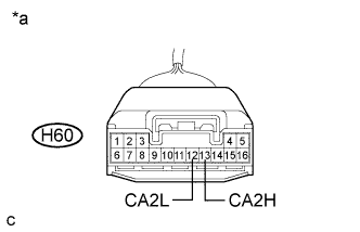
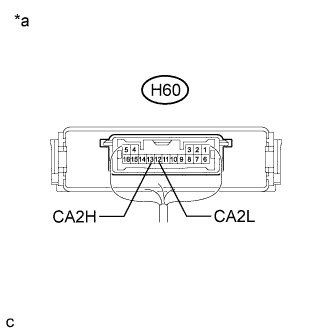
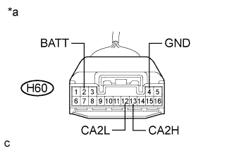
Text in Illustration *a Component with harness connected
(Network Gateway ECU)
Measure the resistance according to the value(s) in the table below.
Standard Resistance Tester Connection Condition Specified Condition Result H60-13 (CA2H) - H60-12 (CA2L) Cable disconnected from negative (-) battery terminal 54 to 69 Ω Below 54 Ω:
Short circuit between bus lines
70 Ω or higher:
Open circuit in a main bus line
H60-13 (CA2H) - H60-4 (GND) Cable disconnected from negative (-) battery terminal 200 Ω or higher Below 200 Ω:
CANH ground short
H60-12 (CA2L) - H60-4 (GND) Cable disconnected from negative (-) battery terminal 200 Ω or higher Below 200 Ω:
CANL ground short
H60-13 (CA2H) - H60-2 (BATT) Cable disconnected from negative (-) battery terminal 6 kΩ or higher Below 6 kΩ:
CANH +B short
H60-12 (CA2L) - H60-2 (BATT) Cable disconnected from negative (-) battery terminal 6 kΩ or higher Below 6 kΩ:
CANL +B short
Result Result Proceed to OK A Open circuit in CAN main bus line B Short circuit between bus lines C
-
Ground short
-
+B short
D -
B
CHECK FOR OPEN IN SUB BUS 2 MAIN LINES (NETWORK GATEWAY ECU) Click here
C
CHECK FOR SHORT IN SUB BUS 2 LINES (NETWORK GATEWAY ECU) Click here
D
CHECK FOR SHORT IN SUB BUS 2 LINE (CAN J/C RH3 - NETWORK GATEWAY ECU) Click here
A
-
-
RECONFIRM DTC OUTPUT
-
Reconnect the cable to the negative (-) battery terminal.
-
Connect the GTS to the DLC3.
-
Turn the engine switch on (IG).
-
Turn the GTS on.
-
Clear the DTCs.
-
Turn the engine switch off.
-
Turn the engine switch on (IG) and recheck for DTCs.
Result Result Proceed to U1002 is output from network gateway ECU
(GTS display: Gateway)
A Other DTC is output. B
B 
GO TO DIAGNOSIS PROCEDURE INDICATED BY OUTPUT DTC Click here
A 
REPLACE NETWORK GATEWAY ECU Click here
-
-
CHECK FOR OPEN IN SUB BUS 2 MAIN LINES (NETWORK GATEWAY ECU)
-
Text in Illustration *a Front view of wire harness connector
(to Network Gateway ECU)
Disconnect the H60 network gateway ECU connector.
-
Measure the resistance according to the value(s) in the table below.
Standard Resistance Tester Connection Condition Specified Condition H60-13 (CA2H) - H60-12 (CA2L) Cable disconnected from negative (-) battery terminal 108 to 132 Ω
NG
CHECK FOR OPEN IN SUB BUS 2 MAIN LINES (CAN J/C RH3 - NETWORK GATEWAY ECU) Click here
OK
REPLACE NETWORK GATEWAY ECU Click here
-
-
CHECK FOR OPEN IN SUB BUS 2 MAIN LINES (CAN J/C RH3 - NETWORK GATEWAY ECU)
-
Reconnect the H60 network gateway ECU connector.
-
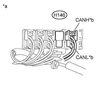
Disconnect the H146 wire harness connector.
-
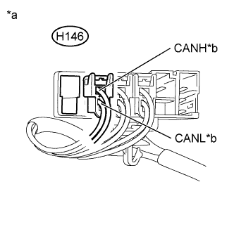
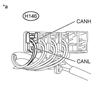
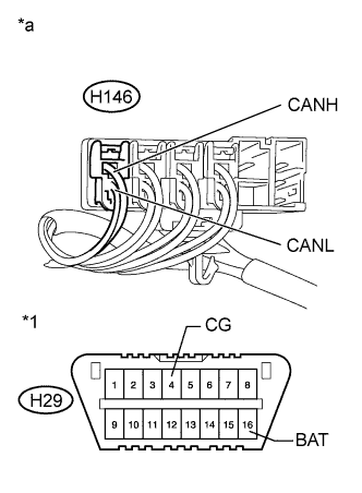
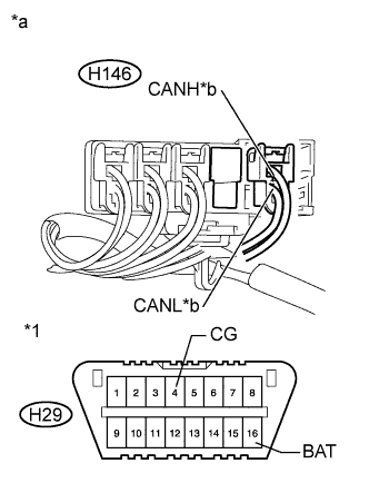
Text in Illustration *a Rear view of wire harness connector
(to CAN Junction Connector RH3)
*b to Network Gateway ECU Measure the resistance according to the value(s) in the table below.
Standard Resistance Tester Connection Condition Specified Condition H146-1 (CANH) - H146-2 (CANL) Cable disconnected from negative (-) battery terminal 108 to 132 Ω Note
-
Before disconnecting the connector, make a note of where it is connected.
-
Reconnect the connector to its original position.
-
NG
REPAIR OR REPLACE CAN MAIN BUS LINE OR CONNECTOR (CAN J/C RH3 - NETWORK GATEWAY ECU)
OK
-
-
CHECK FOR OPEN IN SUB BUS 2 MAIN LINES (CAN J/C RH3)
-
Reconnect the H146 wire harness connector.
-
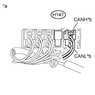
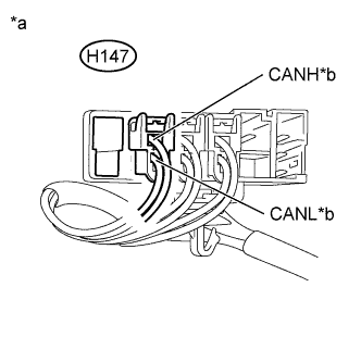
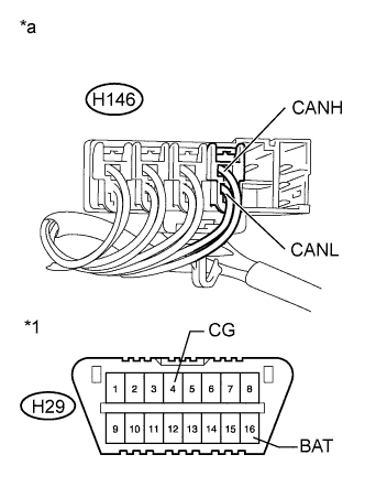
Text in Illustration *a Rear view of wire harness connector
(to CAN Junction Connector RH3)
*b to CAN No. 3 Junction Connector Disconnect the H147 wire harness connector.
-
Measure the resistance according to the value(s) in the table below.
Standard Resistance Tester Connection Condition Specified Condition H147-1 (CANH) - H147-2 (CANL) Cable disconnected from negative (-) battery terminal 108 to 132 Ω Note
-
Before disconnecting the connector, make a note of where it is connected.
-
Reconnect the connector to its original position.
-
NG
CHECK FOR OPEN IN SUB BUS 2 MAIN LINES (CAN J/C RH3 - CAN NO. 3 J/C) Click here
OK
REPLACE CAN JUNCTION CONNECTOR RH3
-
-
CHECK FOR OPEN IN SUB BUS 2 MAIN LINES (CAN J/C RH3 - CAN NO. 3 J/C)
-
Reconnect the H147 wire harness connector.
-
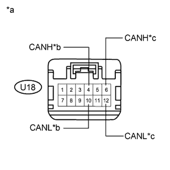
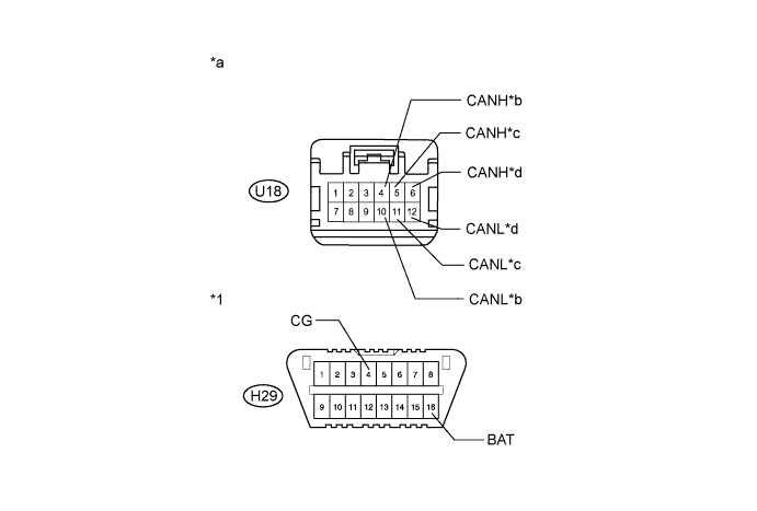
Text in Illustration *a Front view of wire harness connector
(to CAN No. 3 Junction Connector)
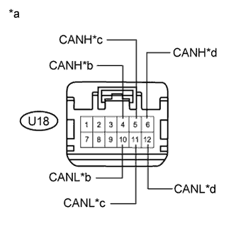
*b to CAN Junction Connector RH3 *c to CAN No. 4 Junction Connector Disconnect the U18 CAN No. 3 junction connector.
-
Measure the resistance according to the value(s) in the table below.
Standard Resistance Tester Connection Condition Specified Condition U18-4 (CANH) - U18-10 (CANL) Cable disconnected from negative (-) battery terminal 108 to 132 Ω U18-6 (CANH) - U18-12 (CANL) Cable disconnected from negative (-) battery terminal 108 to 132 Ω Result Result Proceed to OK A NG (to CAN junction connector RH3 main bus line) B NG (to CAN No. 4 junction connector main bus line) C
B
REPAIR OR REPLACE CAN MAIN BUS LINE OR CONNECTOR (CAN J/C RH3 - CAN NO. 3 J/C)
C
CHECK FOR OPEN IN SUB BUS 2 MAIN LINES (CAN NO. 3 J/C - CAN NO. 4 J/C) Click here
A
REPLACE CAN NO. 3 JUNCTION CONNECTOR
-
-
CHECK FOR OPEN IN SUB BUS 2 MAIN LINES (CAN NO. 3 J/C - CAN NO. 4 J/C)
-
Reconnect the U18 CAN No. 3 junction connector.
-
Disconnect the U19 CAN No. 4 junction connector.
-
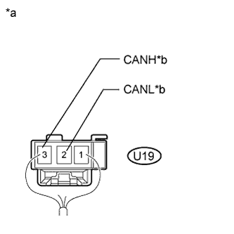
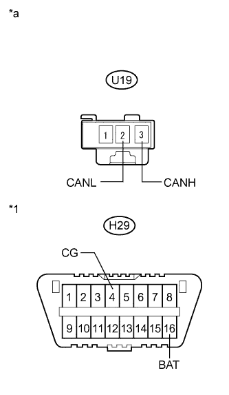
Text in Illustration *a Rear view of wire harness connector
(to CAN No. 4 Junction Connector)
*b to CAN No. 3 Junction Connector Measure the resistance according to the value(s) in the table below.
Standard Resistance Tester Connection Condition Specified Condition U19-3 (CANH) - U19-2 (CANL) Cable disconnected from negative (-) battery terminal 108 to 132 Ω
NG
REPAIR OR REPLACE CAN MAIN BUS LINE OR CONNECTOR (CAN NO. 3 J/C - CAN NO. 4 J/C)
OK
REPLACE CAN NO. 4 JUNCTION CONNECTOR
-
-
CHECK FOR SHORT IN SUB BUS 2 LINES (NETWORK GATEWAY ECU)
-
Text in Illustration *a Front view of wire harness connector
(to Network Gateway ECU)
Disconnect the H60 network gateway ECU connector.
-
Measure the resistance according to the value(s) in the table below.
Standard Resistance Tester Connection Condition Specified Condition H60-13 (CA2H) - H60-12 (CA2L) Cable disconnected from negative (-) battery terminal 108 to 132 Ω
NG
CHECK FOR SHORT IN SUB BUS 2 LINES (CAN J/C RH3 - NETWORK GATEWAY ECU) Click here
OK
REPLACE NETWORK GATEWAY ECU Click here
-
-
CHECK FOR SHORT IN SUB BUS 2 LINES (CAN J/C RH3 - NETWORK GATEWAY ECU)
-
Reconnect the H60 network gateway ECU connector.
-
Disconnect the H146 wire harness connector.
-
Text in Illustration *a Rear view of wire harness connector
(to CAN Junction Connector RH3)
*b to Network Gateway ECU Measure the resistance according to the value(s) in the table below.
Standard Resistance Tester Connection Condition Specified Condition H146-1 (CANH) - H146-2 (CANL) Cable disconnected from negative (-) battery terminal 108 to 132 Ω Note
-
Before disconnecting the connector, make a note of where it is connected.
-
Reconnect the connector to its original position.
-
NG
REPAIR OR REPLACE CAN MAIN BUS LINE OR CONNECTOR (CAN J/C RH3 - NETWORK GATEWAY ECU)
OK
-
-
CHECK FOR SHORT IN SUB BUS 2 LINES (BRANCH LINE)
-
Reconnect the H146 wire harness connector.
-
Text in Illustration *a Component with harness connected
(CAN Junction Connector RH3)
Connect the probes of an ohmmeter to terminals 1 (CANH) and 2 (CANL) of the network gateway ECU main line harness connector.
-
While observing the resistance value shown on the tester, disconnect connectors (H148 and H150) from the CAN junction connector RH3 one by one until the resistance becomes normal (between 54 and 69 Ω).

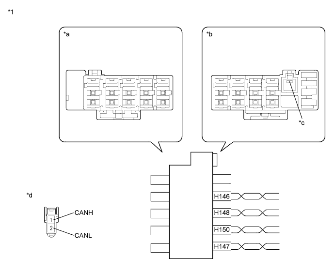
Text in Illustration *1 CAN Junction Connector RH3 - - *a Junction Connector A Side *b Junction Connector B Side *c Ground Terminal *d Front view of wire harness connector
(to CAN Junction Connector RH3)
Wiring Color CAN Junction Connector RH3 Side Code Color (CANH Side) Color (CANL Side) Network gateway ECU H146 L LG Seat belt control ECU H148 G LG CAN main bus line (bus line connecting CAN junction connector RH3 and CAN No. 3 junction connector) H147 B LG Driving support ECU assembly H150 R LG Note
Do not reconnect the disconnected connectors until this inspection is complete because there may be a short in 2 or more branch lines.
Result Result Proceed to The resistance is still below 54 Ω when all the specified connectors are disconnected. (There are no shorts between a pair of branch lines.) A The resistance becomes normal (between 54 and 69 Ω) when a connector is disconnected. (There is a short between one or more pairs of branch lines.) B -
When there is a short in one or more of the branch lines:
-
Reconnect all of the connectors to the CAN junction connectors, except for the one that was disconnected last (the short-circuited bus line). Check that the resistance shown on the tester is normal (between 54 and 69 Ω) to confirm that there is a short in the one branch line only.
Tech Tips
-
Connectors that connect to the CAN junction connector can be distinguished by the color of their CAN bus lines.
-
Reconnecting the connectors to non-original positions on the CAN junction connector does not affect system performance. However, it is preferred to reconnect the connectors to their original positions to avoid negative effects on the wiring such as tension on the wiring harnesses, and to make future maintenance easier.
-
-
B
CHECK FOR SHORT IN SUB BUS 2 LINE (ECUS) Click here
A
-
-
CHECK FOR SHORT IN SUB BUS 2 LINES (CAN J/C RH3)
-
Disconnect the H147 wire harness connector.
-
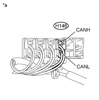
Text in Illustration *a Component with harness connected
(CAN Junction Connector RH3)
Measure the resistance according to the value(s) in the table below.
Standard Resistance Tester Connection Condition Specified Condition H146-1 (CANH) - H146-2 (CANL) Cable disconnected from negative (-) battery terminal 108 to 132 Ω Note
-
Before disconnecting the connector, make a note of where it is connected.
-
Reconnect the connector to its original position.
-
NG
REPLACE CAN JUNCTION CONNECTOR RH3
OK
-
-
CHECK FOR SHORT IN SUB BUS 2 LINES (CAN J/C RH3 - CAN NO. 3 J/C)
-
Reconnect the H147 wire harness connector.
-
Disconnect the U18 CAN No. 3 junction connector.
-

Text in Illustration *a Front view of wire harness connector
(to CAN No. 3 Junction Connector)
*b to CAN Junction Connector RH3 *c to Blind Spot Monitor Sensor LH* *d to CAN No. 4 Junction Connector Measure the resistance according to the value(s) in the table below.
Standard Resistance Tester Connection Condition Specified Condition U18-4 (CANH) - U18-10 (CANL) Cable disconnected from negative (-) battery terminal 108 to 132 Ω U18-5 (CANH) - U18-11 (CANL) Cable disconnected from negative (-) battery terminal 200 Ω or higher U18-6 (CANH) - U18-12 (CANL) Cable disconnected from negative (-) battery terminal 108 to 132 Ω
-
*: w/ Blind spot monitor system
Result Result Proceed to OK A NG (to CAN junction connector RH3 main bus line) B NG (to CAN No. 4 junction connector main bus line) C NG (to Blind spot monitor sensor LH) D -
B
REPAIR OR REPLACE CAN MAIN BUS LINE OR CONNECTOR (CAN J/C RH3 - CAN NO. 3 J/C)
C
CHECK FOR SHORT IN SUB BUS 2 LINES (CAN NO. 3 J/C - CAN NO. 4 J/C) Click here
D
CHECK FOR SHORT IN SUB BUS 2 LINE (ECUS) Click here
A
REPLACE CAN NO. 3 JUNCTION CONNECTOR
-
-
CHECK FOR SHORT IN SUB BUS 2 LINES (CAN NO. 3 J/C - CAN NO. 4 J/C)
-
Reconnect the U18 CAN No. 3 junction connector.
-
Disconnect the U19 CAN No. 4 junction connector.
-
Text in Illustration *a Rear view of wire harness connector
(to CAN No. 4 Junction Connector)
*b to CAN No. 3 Junction Connector Measure the resistance according to the value(s) in the table below.
Standard Resistance Tester Connection Condition Specified Condition U19-3 (CANH) - U19-2 (CANL) Cable disconnected from negative (-) battery terminal 108 to 132 Ω
NG
REPAIR OR REPLACE CAN MAIN BUS LINE OR CONNECTOR (CAN NO. 3 J/C - CAN NO. 4 J/C)
OK
REPLACE CAN NO. 4 JUNCTION CONNECTOR
-
-
CHECK FOR SHORT IN SUB BUS 2 LINE (ECUS)
-
Reconnect all wire harness connectors (CAN junction connector RH3 and CAN No. 3 junction connector).
-
Disconnect the connector that includes terminals CANH and CANL from the ECU (or sensor) to which the short-circuited branch line is connected Click here.
-
Text in Illustration *a Component with harness connected
(Network Gateway ECU)
Measure the resistance according to the value(s) in the table below.
Standard Resistance Tester Connection Condition Specified Condition H60-13 (CA2H) - H60-12 (CA2L) Cable disconnected from negative (-) battery terminal 54 to 69 Ω Tech Tips
-
If the resistance becomes normal (between 54 and 69 Ω) when the connector is disconnected from the ECU (or sensor), there may be a short in the ECU (or sensor).
-
If the resistance does not become normal (between 54 and 69 Ω) when the connector is disconnected from the ECU (or sensor), repair or replace the short-circuited branch line or connector.
-
NG
REPAIR OR REPLACE CORRESPONDING ECU OR SENSOR BRANCH LINES OR CONNECTOR
OK
REPLACE CORRESPONDING ECU OR SENSOR
-
-
CHECK FOR SHORT IN SUB BUS 2 LINE (CAN J/C RH3 - NETWORK GATEWAY ECU)
-
Disconnect the H146 wire harness connector.
-
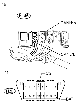
Text in Illustration *1 DLC3 *a Rear view of wire harness connector
(to CAN Junction Connector RH3)
*b to Network Gateway ECU Measure the resistance according to the value(s) in the table below.
Standard Resistance Tester Connection Condition Specified Condition Result H146-1 (CANH) - H29-4 (CG) Cable disconnected from negative (-) battery terminal 200 Ω or higher Below 200 Ω:
CANH ground short
H146-2 (CANL) - H29-4 (CG) Cable disconnected from negative (-) battery terminal 200 Ω or higher Below 200 Ω:
CANL ground short
H146-1 (CANH) - H29-16 (BAT) Cable disconnected from negative (-) battery terminal 6 kΩ or higher Below 6 kΩ:
CANH +B short
H146-2 (CANL) - H29-16 (BAT) Cable disconnected from negative (-) battery terminal 6 kΩ or higher Below 6 kΩ:
CANL +B short
Note
-
Before disconnecting the connector, make a note of where it is connected.
-
Reconnect the connector to its original position.
Tech Tips
-
It is only necessary to perform the inspection in the above table for the result (short circuit) that was obtained in the Check Sub Bus 2 inspection.
-
Find the necessary inspection from the Result column that matches the result in the Specified Condition column from the Check Sub Bus 2 inspection.
-
NG
CHECK FOR SHORT IN SUB BUS LINE (CAN J/C RH3 - NETWORK GATEWAY ECU) Click here
OK
CHECK FOR SHORT IN SUB BUS 2 LINE (BRANCH LINE)
-
-
CHECK FOR SHORT IN SUB BUS 2 LINE (BRANCH LINE)
-
Reconnect the H146 wire harness connector.
-
Text in Illustration *1 DLC3 *a Component with harness connected
(CAN Junction Connector RH3)
Connect the probes of an ohmmeter to terminals 1 (CANH) and 2 (CANL) of the wire harness connector (H146) and CG or BAT of the DLC3.
Tech Tips
It is only necessary to perform the inspection for the result (short circuit) that was obtained in the Check Sub Bus 2 inspection.
-
While observing the resistance value shown on the ohmmeter, disconnect branch line connectors (H148 and H150) from the CAN junction connector RH3 until the resistance becomes normal (6 kΩ or higher (for +B short) or 200 Ω or higher (for ground short)).
Text in Illustration *1 CAN Junction Connector RH3 - - *a Junction Connector A Side *b Junction Connector B Side *c Ground Terminal *d Front view of wire harness connector
(to CAN Junction Connector RH3)
Wiring Color CAN Junction Connector RH3 Side Code Color (CANH Side) Color (CANL Side) Network gateway ECU H146 L LG Seat belt control ECU H148 G LG CAN main bus line (bus line connecting CAN junction connector RH3 and CAN No. 3 junction connector) H147 B LG Driving support ECU assembly H150 R LG Result Result Proceed to The resistance between terminals CA2H and BAT, or the resistance between terminals CA2L and BAT is still below 6 kΩ when all the specified connectors are disconnected from the CAN junction connector.
(There is no short to +B in the branch lines.)
A The resistance between terminals CA2H and GND, or the resistance between terminals CA2L and GND is still below 200 Ω when all the specified connectors are disconnected from the CAN junction connector.
(There is no short to GND in the branch lines.)
The resistance between terminals CA2H and BAT, or the resistance between terminals CA2L and BAT becomes normal (6 kΩ or higher) when a connector is disconnected from the CAN junction connector.
(There is a short to +B in one of the areas related to one or more of the disconnected branch lines.)
B The resistance between terminals CA2H and GND, or the resistance between terminals CA2L and GND becomes normal (200 Ω or higher) when a connector is disconnected from the CAN junction connector.
(There is a short to GND in one of the areas related to one or more of the disconnected branch lines.)
B
CHECK CAN BUS LINE (ECUS) Click here
A
-
-
CHECK FOR SHORT IN SUB BUS 2 LINE (CAN J/C RH3)
-
Disconnect the H147 wire harness connector.
-
Text in Illustration *1 DLC3 *a Component with harness connected
(CAN Junction Connector RH3)
Measure the resistance according to the value(s) in the table below.
Standard Resistance Tester Connection Condition Specified Condition Result H146-1 (CANH) - H29-4 (CG) Cable disconnected from negative (-) battery terminal 200 Ω or higher Below 200 Ω:
CANH ground short
H146-2 (CANL) - H29-4 (CG) Cable disconnected from negative (-) battery terminal 200 Ω or higher Below 200 Ω:
CANL ground short
H146-1 (CANH) - H29-16 (BAT) Cable disconnected from negative (-) battery terminal 6 kΩ or higher Below 6 kΩ:
CANH +B short
H146-2 (CANL) - H29-16 (BAT) Cable disconnected from negative (-) battery terminal 6 kΩ or higher Below 6 kΩ:
CANL +B short
Note
-
Before disconnecting the connector, make a note of where it is connected.
-
Reconnect the connector to its original position.
Tech Tips
-
It is only necessary to perform the inspection in the above table for the result (short circuit) that was obtained in the Check Sub Bus 2 inspection.
-
Find the necessary inspection from the Result column that matches the result in the Specified Condition column from the Check Sub Bus 2 inspection.
-
NG
REPLACE CAN JUNCTION CONNECTOR RH3
OK
-
-
CHECK FOR SHORT IN CAN BUS LINE (CAN J/C RH3 - CAN NO. 3 J/C)
-
Disconnect the U18 CAN No. 3 junction connector.
-
Measure the resistance according to the value(s) in the table below.
Standard Resistance Tester Connection Condition Specified Condition Purpose Connected to U18-4 (CANH) - H29-4 (CG) Cable disconnected from negative (-) battery terminal 200 Ω or higher Inspection for CANH ground short CAN junction connector RH3 U18-10 (CANL) - H29-4 (CG) Cable disconnected from negative (-) battery terminal 200 Ω or higher Inspection for CANL ground short U18-5 (CANH) - H29-4 (CG) Cable disconnected from negative (-) battery terminal 200 Ω or higher Inspection for CANH ground short Blind spot monitor sensor LH* U18-11 (CANL) - H29-4 (CG) Cable disconnected from negative (-) battery terminal 200 Ω or higher Inspection for CANL ground short U18-6 (CANH) - H29-4 (CG) Cable disconnected from negative (-) battery terminal 200 Ω or higher Inspection for CANH ground short CAN No. 4 junction connector U18-12 (CANL) - H29-4 (CG) Cable disconnected from negative (-) battery terminal 200 Ω or higher Inspection for CANL ground short U18-4 (CANH) - H29-16 (BAT) Cable disconnected from negative (-) battery terminal 6 kΩ or higher Inspection for CANH +B short CAN junction connector RH3 U18-10 (CANL) - H29-16 (BAT) Cable disconnected from negative (-) battery terminal 6 kΩ or higher Inspection for CANL +B short U18-5 (CANH) - H29-16 (BAT) Cable disconnected from negative (-) battery terminal 6 kΩ or higher Inspection for CANH +B short Blind spot monitor sensor LH* U18-11 (CANL) - H29-16 (BAT) Cable disconnected from negative (-) battery terminal 6 kΩ or higher Inspection for CANL +B short U18-6 (CANH) - H29-16 (BAT) Cable disconnected from negative (-) battery terminal 6 kΩ or higher Inspection for CANH +B short CAN No. 4 junction connector U18-12 (CANL) - H29-16 (BAT) Cable disconnected from negative (-) battery terminal 6 kΩ or higher Inspection for CANL +B short
-
*: w/ Blind spot monitor system
Text in Illustration *1 DLC3 - - *a Front view of wire harness connector
(to CAN No. 3 Junction Connector)
*b to CAN Junction Connector RH3 *c to Blind Spot Monitor Sensor LH* *d to CAN No. 4 Junction Connector
-
*: w/ Blind spot monitor system
Result Result Proceed to OK A NG (to CAN junction connector RH3 main bus line) B NG (to CAN No. 4 junction connector main bus line) C NG (to Blind spot monitor sensor LH) D Tech Tips
-
It is only necessary to perform the inspection in the above table for the result (short circuit) that was obtained in the Check Sub Bus 2 inspection.
-
Find the necessary inspection from the Purpose column that matches the result in the Result column from the Check Sub Bus 2 inspection.
-
B
REPAIR OR REPLACE CAN MAIN BUS LINE OR CONNECTOR (CAN J/C RH3 - CAN NO. 3 J/C)
C
CHECK FOR SHORT IN CAN BUS LINE (CAN NO. 3 J/C - CAN NO. 4 J/C) Click here
D
CHECK CAN BUS LINE (ECUS) Click here
A
REPLACE CAN NO. 3 JUNCTION CONNECTOR
-
-
CHECK FOR SHORT IN CAN BUS LINE (CAN NO. 3 J/C - CAN NO. 4 J/C)
-
Disconnect the U19 CAN No. 4 junction connector.
-
Text in Illustration *1 DLC3 *a Front view of wire harness connector
(to CAN No. 4 Junction Connector)
Measure the resistance according to the value(s) in the table below.
Standard Resistance Tester Connection Condition Specified Condition Result U19-3 (CANH) - H29-4 (CG) Cable disconnected from negative (-) battery terminal 200 Ω or higher Below 200 Ω:
CANH ground short
U19-2 (CANL) - H29-4 (CG) Cable disconnected from negative (-) battery terminal 200 Ω or higher Below 200 Ω:
CANL ground short
U19-3 (CANH) - H29-16 (BAT) Cable disconnected from negative (-) battery terminal 6 kΩ or higher Below 6 kΩ:
CANH +B short
U19-2 (CANL) - H29-16 (BAT) Cable disconnected from negative (-) battery terminal 6 kΩ or higher Below 6 kΩ:
CANL +B short
Tech Tips
-
It is only necessary to perform the inspection in the above table for the result (short circuit) that was obtained in the Check Sub Bus 2 inspection.
-
Find the necessary inspection from the Result column that matches the result in the Specified Condition column from the Check Sub Bus 2 inspection.
-
NG
REPAIR OR REPLACE CAN MAIN BUS LINE OR CONNECTOR (CAN NO. 3 J/C - CAN NO. 4 J/C)
OK
REPLACE CAN NO. 4 JUNCTION CONNECTOR
-
-
CHECK CAN BUS LINE (ECUS)
-
Reconnect all wire harness connectors (CAN junction connector RH3 and CAN No. 3 junction connector).
-
Disconnect the connector that includes terminals CANH and CANL from the ECU to which the bus line shorted to B+ or shorted to GND is connected Click here.
-
Text in Illustration *a Component with harness connected
(Network Gateway ECU)
Measure the resistance according to the value(s) in the table below.
Standard Resistance Tester Connection Condition Specified Condition Result H60-13 (CA2H) - H60-4 (GND) Cable disconnected from negative (-) battery terminal 200 Ω or higher Below 200 Ω:
CANH ground short
H60-12 (CA2L) - H60-4 (GND) Cable disconnected from negative (-) battery terminal 200 Ω or higher Below 200 Ω:
CANL ground short
H60-13 (CA2H) - H60-2 (BATT) Cable disconnected from negative (-) battery terminal 6 kΩ or higher Below 6 kΩ:
CANH +B short
H60-12 (CA2L) - H60-2 (BATT) Cable disconnected from negative (-) battery terminal 6 kΩ or higher Below 6 kΩ:
CANL +B short
Tech Tips
-
It is only necessary to perform the inspection in the above table for the result (short circuit) that was obtained in the Check Sub Bus 2 inspection.
-
If the resistance becomes abnormal when an ECU connector is reconnected, there may be a short in the ECU.
-
NG
REPAIR OR REPLACE CORRESPONDING ECU OR SENSOR BRANCH LINES OR CONNECTOR
OK
REPLACE CORRESPONDING ECU OR SENSOR
-
-
CHECK FOR SHORT IN SUB BUS LINE (CAN J/C RH3 - NETWORK GATEWAY ECU)
-
Disconnect the H60 network gateway ECU connector.
-
Text in Illustration *a Front view of wire harness connector
(to Network Gateway ECU)
Measure the resistance according to the value(s) in the table below.
Standard Resistance Tester Connection Condition Specified Condition Result H60-13 (CA2H) - H60-4 (GND) Cable disconnected from negative (-) battery terminal 200 Ω or higher Below 200 Ω:
CANH ground short
H60-12 (CA2L) - H60-4 (GND) Cable disconnected from negative (-) battery terminal 200 Ω or higher Below 200 Ω:
CANL ground short
H60-13 (CA2H) - H60-2 (BATT) Cable disconnected from negative (-) battery terminal 6 kΩ or higher Below 6 kΩ:
CANH +B short
H60-12 (CA2L) - H60-2 (BATT) Cable disconnected from negative (-) battery terminal 6 kΩ or higher Below 6 kΩ:
CANL +B short
Tech Tips
-
It is only necessary to perform the inspection in the above table for the result (short circuit) that was obtained in the Check Sub Bus 2 inspection.
-
Find the necessary inspection from the Result column that matches the result in the Specified Condition column from the Check Sub Bus 2 inspection.
-
NG
REPAIR OR REPLACE CAN MAIN BUS LINE OR CONNECTOR (CAN J/C RH3 - NETWORK GATEWAY ECU)
OK
REPLACE NETWORK GATEWAY ECU Click here
-
-
CHECK SUB BUS 2
-
Disconnect the cable from the negative (-) battery terminal.
-
Text in Illustration *a Component with harness connected
(Network Gateway ECU)
Measure the resistance according to the value(s) in the table below.
Standard Resistance Tester Connection Condition Specified Condition Result H60-13 (CA2H) - H60-12 (CA2L) Cable disconnected from negative (-) battery terminal 54 to 69 Ω Below 54 Ω:
Short circuit between bus lines
70 Ω or higher:
Open circuit in a main bus line
H60-13 (CA2H) - H60-4 (GND) Cable disconnected from negative (-) battery terminal 200 Ω or higher Below 200 Ω:
CANH ground short
H60-12 (CA2L) - H60-4 (GND) Cable disconnected from negative (-) battery terminal 200 Ω or higher Below 200 Ω:
CANL ground short
H60-13 (CA2H) - H60-2 (BATT) Cable disconnected from negative (-) battery terminal 6 kΩ or higher Below 6 kΩ:
CANH +B short
H60-12 (CA2L) - H60-2 (BATT) Cable disconnected from negative (-) battery terminal 6 kΩ or higher Below 6 kΩ:
CANL +B short
Result Result Proceed to OK A Open circuit in CAN main bus line B Short circuit between bus lines C
-
Ground short
-
+B short
D -
B
CHECK FOR OPEN IN SUB BUS 2 MAIN LINES (NETWORK GATEWAY ECU) Click here
C
CHECK FOR SHORT IN SUB BUS 2 LINES (NETWORK GATEWAY ECU) Click here
D
CHECK FOR SHORT IN CAN BUS LINE (CAN NO. 2 J/C - NETWORK GATEWAY ECU) Click here
A
-
-
RECONFIRM DTC OUTPUT
-
Reconnect the cable to the negative (-) battery terminal.
-
Connect the GTS to the DLC3.
-
Turn the engine switch on (IG).
-
Turn the GTS on.
-
Clear the DTCs.
-
Turn the engine switch off.
-
Turn the engine switch on (IG) and recheck for DTCs.
Result Result Proceed to U1002 is output from network gateway ECU
(GTS display: Gateway)
A Other DTC is output. B
B
GO TO DIAGNOSIS PROCEDURE INDICATED BY OUTPUT DTC Click here
A
REPLACE NETWORK GATEWAY ECU Click here
-
-
CHECK FOR OPEN IN SUB BUS 2 MAIN LINES (NETWORK GATEWAY ECU)
-
Text in Illustration *a Front view of wire harness connector
(to Network Gateway ECU)
Disconnect the H60 network gateway ECU connector.
-
Measure the resistance according to the value(s) in the table below.
Standard Resistance Tester Connection Condition Specified Condition H60-13 (CA2H) - H60-12 (CA2L) Cable disconnected from negative (-) battery terminal 108 to 132 Ω
NG
CHECK FOR OPEN IN SUB BUS 2 MAIN LINES (CAN NO. 2 J/C - NETWORK GATEWAY ECU) Click here
OK
REPLACE NETWORK GATEWAY ECU Click here
-
-
CHECK FOR OPEN IN SUB BUS 2 MAIN LINES (CAN NO. 2 J/C - NETWORK GATEWAY ECU)
-
Disconnect the T13 CAN No. 2 junction connector.
-
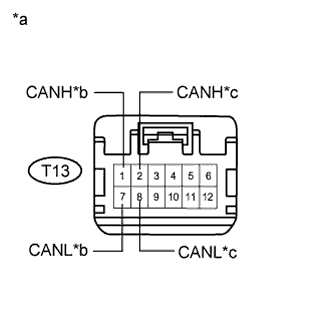
Text in Illustration *a Front view of wire harness connector
(to CAN No. 2 Junction Connector)
*b to Network Gateway ECU *c to CAN Junction Connector RH3 Measure the resistance according to the value(s) in the table below.
Standard Resistance Tester Connection Condition Specified Condition T13-1 (CANH) - T13-7 (CANL) Cable disconnected from negative (-) battery terminal 108 to 132 Ω T13-2 (CANH) - T13-8 (CANL) Cable disconnected from negative (-) battery terminal 108 to 132 Ω Result Result Proceed to OK A NG (to Network gateway ECU CAN main bus line) B NG (to CAN junction connector RH3 CAN main bus line) C
B
REPAIR OR REPLACE CAN MAIN BUS LINE OR CONNECTOR (CAN NO. 2 J/C - NETWORK GATEWAY ECU)
C
CHECK FOR OPEN IN SUB BUS 2 MAIN LINES (CAN J/C RH3 - CAN NO. 2 J/C) Click here
A
REPLACE CAN NO. 2 JUNCTION CONNECTOR
-
-
CHECK FOR OPEN IN SUB BUS 2 MAIN LINES (CAN J/C RH3 - CAN NO. 2 J/C)
-
Reconnect the T13 CAN No. 2 junction connector.
-
Disconnect the H150 wire harness connector.
-
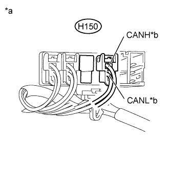
Text in Illustration *a Rear view of wire harness connector
(to CAN Junction Connector RH3)
*b to CAN No. 2 Junction Connector Measure the resistance according to the value(s) in the table below.
Standard Resistance Tester Connection Condition Specified Condition H150-1 (CANH) - H150-2 (CANL) Cable disconnected from negative (-) battery terminal 108 to 132 Ω Note
-
Before disconnecting the connector, make a note of where it is connected.
-
Reconnect the connector to its original position.
-
NG
REPAIR OR REPLACE CAN MAIN BUS LINE OR CONNECTOR (CAN J/C RH3 - CAN NO. 2 J/C)
OK
-
-
CHECK FOR OPEN IN SUB BUS 2 MAIN LINES (CAN J/C RH3)
-
Reconnect the H150 wire harness connector.
-
Text in Illustration *a Rear view of wire harness connector
(to CAN Junction Connector RH3)
*b to CAN No. 3 Junction Connector Disconnect the H147 wire harness connector.
-
Measure the resistance according to the value(s) in the table below.
Standard Resistance Tester Connection Condition Specified Condition H147-1 (CANH) - H147-2 (CANL) Cable disconnected from negative (-) battery terminal 108 to 132 Ω Note
-
Before disconnecting the connector, make a note of where it is connected.
-
Reconnect the connector to its original position.
-
NG
CHECK FOR OPEN IN SUB BUS 2 MAIN LINES (CAN J/C RH3 - CAN NO. 3 J/C) Click here
OK
REPLACE CAN JUNCTION CONNECTOR RH3
-
-
CHECK FOR OPEN IN SUB BUS 2 MAIN LINES (CAN J/C RH3 - CAN NO. 3 J/C)
-
Reconnect the H147 wire harness connector.
-

Text in Illustration *a Front view of wire harness connector
(to CAN No. 3 Junction Connector)
*b to CAN Junction Connector RH3 *c to CAN No. 4 Junction Connector Disconnect the U18 CAN No. 3 junction connector.
-
Measure the resistance according to the value(s) in the table below.
Standard Resistance Tester Connection Condition Specified Condition U18-4 (CANH) - U18-10 (CANL) Cable disconnected from negative (-) battery terminal 108 to 132 Ω U18-6 (CANH) - U18-12 (CANL) Cable disconnected from negative (-) battery terminal 108 to 132 Ω Result Result Proceed to OK A NG (to CAN junction connector RH3 main bus line) B NG (to CAN No. 4 junction connector main bus line) C
B
REPAIR OR REPLACE CAN MAIN BUS LINE OR CONNECTOR (CAN J/C RH3 - CAN NO. 3 J/C)
C
CHECK FOR OPEN IN SUB BUS 2 MAIN LINES (CAN NO. 3 J/C - CAN NO. 4 J/C) Click here
A
REPLACE CAN NO. 3 JUNCTION CONNECTOR
-
-
CHECK FOR OPEN IN SUB BUS 2 MAIN LINES (CAN NO. 3 J/C - CAN NO. 4 J/C)
-
Reconnect the U18 CAN No. 3 junction connector.
-
Disconnect the U19 CAN No. 4 junction connector.
-
Text in Illustration *a Rear view of wire harness connector
(to CAN No. 4 Junction Connector)
*b to CAN No. 3 Junction Connector Measure the resistance according to the value(s) in the table below.
Standard Resistance Tester Connection Condition Specified Condition U19-3 (CANH) - U19-2 (CANL) Cable disconnected from negative (-) battery terminal 108 to 132 Ω
NG
REPAIR OR REPLACE CAN MAIN BUS LINE OR CONNECTOR (CAN NO. 3 J/C - CAN NO. 4 J/C)
OK
REPLACE CAN NO. 4 JUNCTION CONNECTOR
-
-
CHECK FOR SHORT IN SUB BUS 2 LINES (NETWORK GATEWAY ECU)
-
Text in Illustration *a Front view of wire harness connector
(to Network Gateway ECU)
Disconnect the H60 network gateway ECU connector.
-
Measure the resistance according to the value(s) in the table below.
Standard Resistance Tester Connection Condition Specified Condition H60-13 (CA2H) - H60-12 (CA2L) Cable disconnected from negative (-) battery terminal 108 to 132 Ω
NG
CHECK FOR SHORT IN SUB BUS 2 LINES (CAN NO. 2 J/C - NETWORK GATEWAY ECU) Click here
OK
REPLACE NETWORK GATEWAY ECU Click here
-
-
CHECK FOR SHORT IN SUB BUS 2 LINES (CAN NO. 2 J/C - NETWORK GATEWAY ECU)
-
Reconnect the H60 network gateway ECU connector.
-
Disconnect the T13 CAN No. 2 junction connector.
-
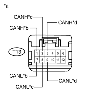
Text in Illustration *a Front view of wire harness connector
(to CAN No. 2 Junction Connector)
*b to Network Gateway ECU *c to CAN Junction Connector RH3 *d to Lane Departure Warning Camera* Measure the resistance according to the value(s) in the table below.
Standard Resistance Tester Connection Condition Specified Condition T13-1 (CANH) - T13-7 (CANL) Cable disconnected from negative (-) battery terminal 108 to 132 Ω T13-2 (CANH) - T13-8 (CANL) Cable disconnected from negative (-) battery terminal 108 to 132 Ω T13-3 (CANH) - T13-9 (CANL) Cable disconnected from negative (-) battery terminal 200 Ω or higher
-
*: w/ Lane departure alert system
Result Result Proceed to OK A NG (to network gateway ECU main bus line) B NG (to CAN junction connector RH3 main bus line) C NG (to lane departure warning camera) D -
B
REPAIR OR REPLACE CAN MAIN BUS LINE OR CONNECTOR (CAN NO. 2 J/C - NETWORK GATEWAY ECU)
C
CHECK FOR SHORT IN SUB BUS 2 LINES (CAN J/C RH3 - CAN NO. 2 J/C) Click here
D
CHECK FOR SHORT IN SUB BUS 2 LINE (ECUS) Click here
A
REPLACE CAN NO. 2 JUNCTION CONNECTOR
-
-
CHECK FOR SHORT IN SUB BUS 2 LINES (CAN J/C RH3 - CAN NO. 2 J/C)
-
Reconnect the T13 CAN No. 2 junction connector.
-
Disconnect the H150 wire harness connector.
-
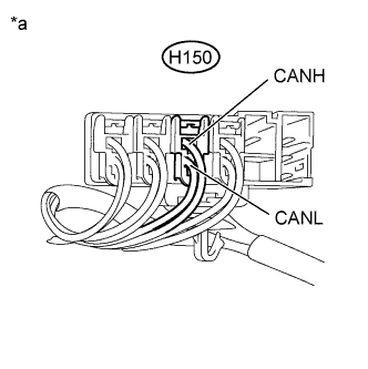
Text in Illustration *a Rear view of wire harness connector
(to CAN Junction Connector RH3)
*b to CAN No. 2 Junction Connector Measure the resistance according to the value(s) in the table below.
Standard Resistance Tester Connection Condition Specified Condition H150-1 (CANH) - H150-2 (CANL) Cable disconnected from negative (-) battery terminal 108 to 132 Ω Note
-
Before disconnecting the connector, make a note of where it is connected.
-
Reconnect the connector to its original position.
-
NG
REPAIR OR REPLACE CAN MAIN BUS LINE OR CONNECTOR (CAN J/C RH3 - CAN NO. 2 J/C)
OK
-
-
CHECK FOR SHORT IN SUB BUS 2 LINES (CAN J/C RH3)
-
Reconnect the H150 wire harness connector.
-
Disconnect the H147 wire harness connector.
-
Text in Illustration *a Component with harness connected
(CAN Junction Connector RH3)
Measure the resistance according to the value(s) in the table below.
Standard Resistance Tester Connection Condition Specified Condition H150-1 (CANH) - H150-2 (CANL) Cable disconnected from negative (-) battery terminal 108 to 132 Ω Note
-
Before disconnecting the connector, make a note of where it is connected.
-
Reconnect the connector to its original position.
-
NG
REPLACE CAN JUNCTION CONNECTOR RH3
OK
-
-
CHECK FOR SHORT IN SUB BUS 2 LINES (CAN NO. 3 J/C)
-
Reconnect the H147 wire harness connector.
-
Disconnect the U18 CAN No. 3 junction connector.
-
Text in Illustration *a Front view of wire harness connector
(to CAN No. 3 Junction Connector)
*b to CAN Junction Connector RH3 *c to Blind Spot Monitor Sensor LH* *d to CAN No. 4 Junction Connector Measure the resistance according to the value(s) in the table below.
Standard Resistance Tester Connection Condition Specified Condition U18-4 (CANH) - U18-10 (CANL) Cable disconnected from negative (-) battery terminal 108 to 132 Ω U18-5 (CANH) - U18-11 (CANL) Cable disconnected from negative (-) battery terminal 200 Ω or higher U18-6 (CANH) - U18-12 (CANL) Cable disconnected from negative (-) battery terminal 108 to 132 Ω
-
*: w/ Blind spot monitor system
Result Result Proceed to OK A NG (to CAN junction connector RH3 main bus line) B NG (to CAN No. 4 junction connector main bus line) C NG (to Blind spot monitor sensor LH) D -
B
REPAIR OR REPLACE CAN MAIN BUS LINE OR CONNECTOR (CAN J/C RH3 - CAN NO. 3 J/C)
C
CHECK FOR SHORT IN SUB BUS 2 LINES (CAN NO. 3 J/C - CAN NO. 4 J/C) Click here
D
CHECK FOR SHORT IN SUB BUS 2 LINE (ECUS) Click here
A
REPLACE CAN NO. 3 JUNCTION CONNECTOR
-
-
CHECK FOR SHORT IN SUB BUS 2 LINES (CAN NO. 3 J/C - CAN NO. 4 J/C)
-
Reconnect the U18 CAN No. 3 junction connector.
-
Disconnect the U19 CAN No. 4 junction connector.
-
Text in Illustration *a Rear view of wire harness connector
(to CAN No. 4 Junction Connector)
*b to CAN No. 3 Junction Connector Measure the resistance according to the value(s) in the table below.
Standard Resistance Tester Connection Condition Specified Condition U19-3 (CANH) - U19-2 (CANL) Cable disconnected from negative (-) battery terminal 108 to 132 Ω
NG
REPAIR OR REPLACE CAN MAIN BUS LINE OR CONNECTOR (CAN NO. 3 J/C - CAN NO. 4 J/C)
OK
REPLACE CAN NO. 4 JUNCTION CONNECTOR
-
-
CHECK FOR SHORT IN SUB BUS 2 LINE (ECUS)
-
Reconnect all wire harness connectors (CAN junction connector RH3, CAN No. 2 junction connector and CAN No. 3 junction connector).
-
Disconnect the connector that includes terminals CANH and CANL from the ECU (or sensor) to which the short-circuited branch line is connected Click here.
-
Text in Illustration *a Component with harness connected
(Network Gateway ECU)
Measure the resistance according to the value(s) in the table below.
Standard Resistance Tester Connection Condition Specified Condition H60-13 (CA2H) - H60-12 (CA2L) Cable disconnected from negative (-) battery terminal 54 to 69 Ω Tech Tips
-
If the resistance becomes normal (between 54 and 69 Ω) when the connector is disconnected from the ECU (or sensor), there may be a short in the ECU (or sensor).
-
If the resistance does not become normal (between 54 and 69 Ω) when the connector is disconnected from the ECU (or sensor), repair or replace the short-circuited branch line or connector.
-
NG
REPAIR OR REPLACE CORRESPONDING ECU OR SENSOR BRANCH LINES OR CONNECTOR
OK
REPLACE CORRESPONDING ECU OR SENSOR
-
-
CHECK FOR SHORT IN CAN BUS LINE (CAN NO. 2 J/C - NETWORK GATEWAY ECU)
-
Disconnect the T13 CAN No. 2 junction connector.
-
Measure the resistance according to the value(s) in the table below.
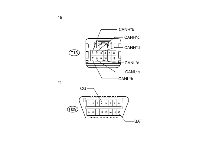
Standard Resistance Tester Connection Condition Specified Condition Purpose Connected to T13-1 (CANH) - H29-4 (CG) Cable disconnected from negative (-) battery terminal 200 Ω or higher Inspection for CANH ground short Network gateway ECU T13-7 (CANL) - H29-4 (CG) Cable disconnected from negative (-) battery terminal 200 Ω or higher Inspection for CANL ground short T13-2 (CANH) - H29-4 (CG) Cable disconnected from negative (-) battery terminal 200 Ω or higher Inspection for CANH ground short CAN junction connector RH3 T13-8 (CANL) - H29-4 (CG) Cable disconnected from negative (-) battery terminal 200 Ω or higher Inspection for CANL ground short T13-3 (CANH) - H29-4 (CG) Cable disconnected from negative (-) battery terminal 200 Ω or higher Inspection for CANH ground short Lane departure warning camera* T13-9 (CANL) - H29-4 (CG) Cable disconnected from negative (-) battery terminal 200 Ω or higher Inspection for CANL ground short T13-1 (CANH) - H29-16 (BAT) Cable disconnected from negative (-) battery terminal 6 kΩ or higher Inspection for CANH +B short Network gateway ECU T13-7 (CANL) - H29-16 (BAT) Cable disconnected from negative (-) battery terminal 6 kΩ or higher Inspection for CANL +B short T13-2 (CANH) - H29-16 (BAT) Cable disconnected from negative (-) battery terminal 6 kΩ or higher Inspection for CANH +B short CAN junction connector RH3 T13-8 (CANL) - H29-16 (BAT) Cable disconnected from negative (-) battery terminal 6 kΩ or higher Inspection for CANL +B short T13-3 (CANH) - H29-16 (BAT) Cable disconnected from negative (-) battery terminal 6 kΩ or higher Inspection for CANH +B short Lane departure warning camera* T13-9 (CANL) - H29-16 (BAT) Cable disconnected from negative (-) battery terminal 6 kΩ or higher Inspection for CANL +B short
-
*: w/ Lane departure alert system
Text in Illustration *1 DLC3 - - *a Front view of wire harness connector
(to CAN No. 2 Junction Connector)
*b to Network Gateway ECU *c to CAN Junction Connector RH3 *d to Lane Departure Warning Camera*
-
*: w/ Lane departure alert system
Result Result Proceed to OK A NG (to CAN junction connector RH3 main bus line) B NG (to Lane departure warning camera) C NG (to Network gateway ECU main bus line) D Tech Tips
-
It is only necessary to perform the inspection in the above table for the result (short circuit) that was obtained in the Check Sub Bus 2 inspection.
-
Find the necessary inspection from the Purpose column that matches the result in the Result column from the Check Sub Bus 2 inspection.
-
B
CHECK FOR SHORT IN SUB BUS 2 LINES (CAN J/C RH3 - CAN NO. 2 J/C) Click here
C
CHECK CAN BUS LINE (ECUS) Click here
D
CHECK FOR SHORT IN SUB BUS LINE (CAN NO. 2 J/C - NETWORK GATEWAY ECU) Click here
A
REPLACE CAN NO. 2 JUNCTION CONNECTOR
-
-
CHECK FOR SHORT IN SUB BUS 2 LINES (CAN J/C RH3 - CAN NO. 2 J/C)
-
Disconnect the H150 wire harness connector.
-
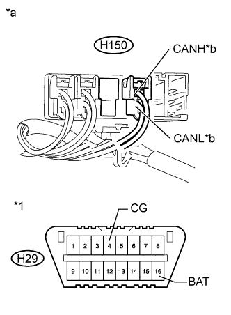
Text in Illustration *1 DLC3 *a Rear view of wire harness connector
(to CAN Junction Connector RH3)
*b to CAN No. 2 Junction Connector Measure the resistance according to the value(s) in the table below.
Standard Resistance Tester Connection Condition Specified Condition Result H150-1 (CANH) - H29-4 (CG) Cable disconnected from negative (-) battery terminal 200 Ω or higher Below 200 Ω:
CANH ground short
H150-2 (CANL) - H29-4 (CG) Cable disconnected from negative (-) battery terminal 200 Ω or higher Below 200 Ω:
CANL ground short
H150-1 (CANH) - H29-16 (BAT) Cable disconnected from negative (-) battery terminal 6 kΩ or higher Below 6 kΩ:
CANH +B short
H150-2 (CANL) - H29-16 (BAT) Cable disconnected from negative (-) battery terminal 6 kΩ or higher Below 6 kΩ:
CANL +B short
Note
-
Before disconnecting the connector, make a note of where it is connected.
-
Reconnect the connector to its original position.
Tech Tips
-
It is only necessary to perform the inspection in the above table for the result (short circuit) that was obtained in the Check Sub Bus 2 inspection.
-
Find the necessary inspection from the Result column that matches the result in the Specified Condition column from the Check Sub Bus 2 inspection.
-
NG
REPAIR OR REPLACE CAN BUS MAIN WIRE OR CONNECTOR (CAN NO. 2 J/C - CAN J/C RH3)
OK
-
-
CHECK FOR SHORT IN SUB BUS 2 LINE (CAN J/C RH3)
-
Reconnect the H150 wire harness connector.
-
Disconnect the H147 wire harness connector.
-
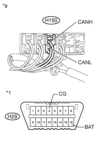
Text in Illustration *1 DLC3 *a Component with harness connected
(CAN Junction Connector RH3)
Measure the resistance according to the value(s) in the table below.
Standard Resistance Tester Connection Condition Specified Condition Result H150-1 (CANH) - H29-4 (CG) Cable disconnected from negative (-) battery terminal 200 Ω or higher Below 200 Ω:
CANH ground short
H150-2 (CANL) - H29-4 (CG) Cable disconnected from negative (-) battery terminal 200 Ω or higher Below 200 Ω:
CANL ground short
H150-1 (CANH) - H29-16 (BAT) Cable disconnected from negative (-) battery terminal 6 kΩ or higher Below 6 kΩ:
CANH +B short
H150-2 (CANL) - H29-16 (BAT) Cable disconnected from negative (-) battery terminal 6 kΩ or higher Below 6 kΩ:
CANL +B short
Note
-
Before disconnecting the connector, make a note of where it is connected.
-
Reconnect the connector to its original position.
Tech Tips
-
It is only necessary to perform the inspection in the above table for the result (short circuit) that was obtained in the Check Sub Bus 2 inspection.
-
Find the necessary inspection from the Result column that matches the result in the Specified Condition column from the Check Sub Bus 2 inspection.
-
NG
REPLACE CAN JUNCTION CONNECTOR RH3
OK
-
-
CHECK FOR SHORT IN CAN BUS LINE (CAN J/C RH3 - CAN NO. 3 J/C)
-
Disconnect the U18 CAN No. 3 junction connector.
-
Measure the resistance according to the value(s) in the table below.
Standard Resistance Tester Connection Condition Specified Condition Purpose Connected to U18-4 (CANH) - H29-4 (CG) Cable disconnected from negative (-) battery terminal 200 Ω or higher Inspection for CANH ground short CAN junction connector RH3 U18-10 (CANL) - H29-4 (CG) Cable disconnected from negative (-) battery terminal 200 Ω or higher Inspection for CANL ground short U18-5 (CANH) - H29-4 (CG) Cable disconnected from negative (-) battery terminal 200 Ω or higher Inspection for CANH ground short Blind spot monitor sensor LH* U18-11 (CANL) - H29-4 (CG) Cable disconnected from negative (-) battery terminal 200 Ω or higher Inspection for CANL ground short U18-6 (CANH) - H29-4 (CG) Cable disconnected from negative (-) battery terminal 200 Ω or higher Inspection for CANH ground short CAN No. 4 junction connector U18-12 (CANL) - H29-4 (CG) Cable disconnected from negative (-) battery terminal 200 Ω or higher Inspection for CANL ground short U18-4 (CANH) - H29-16 (BAT) Cable disconnected from negative (-) battery terminal 6 kΩ or higher Inspection for CANH +B short CAN junction connector RH3 U18-10 (CANL) - H29-16 (BAT) Cable disconnected from negative (-) battery terminal 6 kΩ or higher Inspection for CANL +B short U18-5 (CANH) - H29-16 (BAT) Cable disconnected from negative (-) battery terminal 6 kΩ or higher Inspection for CANH +B short Blind spot monitor sensor LH* U18-11 (CANL) - H29-16 (BAT) Cable disconnected from negative (-) battery terminal 6 kΩ or higher Inspection for CANL +B short U18-6 (CANH) - H29-16 (BAT) Cable disconnected from negative (-) battery terminal 6 kΩ or higher Inspection for CANH +B short CAN No. 4 junction connector U18-12 (CANL) - H29-16 (BAT) Cable disconnected from negative (-) battery terminal 6 kΩ or higher Inspection for CANL +B short
-
*: w/ Blind spot monitor system
Text in Illustration *1 DLC3 - - *a Front view of wire harness connector
(to CAN No. 3 Junction Connector)
*b to CAN Junction Connector RH3 *c to Blind Spot Monitor Sensor LH* *d to CAN No. 4 Junction Connector
-
*: w/ Blind spot monitor system
Result Result Proceed to OK A NG (to CAN junction connector RH3 main bus line) B NG (to CAN No. 4 junction connector main bus line) C NG (to Blind spot monitor sensor LH) D Tech Tips
-
It is only necessary to perform the inspection in the above table for the result (short circuit) that was obtained in the Check Sub Bus 2 inspection.
-
Find the necessary inspection from the Purpose column that matches the result in the Result column from the Check Sub Bus 2 inspection.
-
B
REPAIR OR REPLACE CAN MAIN BUS LINE OR CONNECTOR (CAN J/C RH3 - CAN NO. 3 J/C)
C
CHECK FOR SHORT IN CAN BUS LINE (CAN NO. 3 J/C - CAN NO. 4 J/C) Click here
D
CHECK CAN BUS LINE (ECUS) Click here
A
REPLACE CAN NO. 3 JUNCTION CONNECTOR
-
-
CHECK FOR SHORT IN CAN BUS LINE (CAN NO. 3 J/C - CAN NO. 4 J/C)
-
Disconnect the U19 CAN No. 4 junction connector.
-
Text in Illustration *1 DLC3 *a Front view of wire harness connector
(to CAN No. 4 Junction Connector)
Measure the resistance according to the value(s) in the table below.
Standard Resistance Tester Connection Condition Specified Condition Result U19-3 (CANH) - H29-4 (CG) Cable disconnected from negative (-) battery terminal 200 Ω or higher Below 200 Ω:
CANH ground short
U19-2 (CANL) - H29-4 (CG) Cable disconnected from negative (-) battery terminal 200 Ω or higher Below 200 Ω:
CANL ground short
U19-3 (CANH) - H29-16 (BAT) Cable disconnected from negative (-) battery terminal 6 kΩ or higher Below 6 kΩ:
CANH +B short
U19-2 (CANL) - H29-16 (BAT) Cable disconnected from negative (-) battery terminal 6 kΩ or higher Below 6 kΩ:
CANL +B short
Tech Tips
-
It is only necessary to perform the inspection in the above table for the result (short circuit) that was obtained in the Check Sub Bus 2 inspection.
-
Find the necessary inspection from the Result column that matches the result in the Specified Condition column from the Check Sub Bus 2 inspection.
-
NG
REPAIR OR REPLACE CAN MAIN BUS LINE OR CONNECTOR (CAN NO. 3 J/C - CAN NO. 4 J/C)
OK
REPLACE CAN NO. 4 JUNCTION CONNECTOR
-
-
CHECK CAN BUS LINE (ECUS)
-
Reconnect all wire harness connectors (CAN junction connector RH3, CAN No. 2 junction connector and CAN No. 3 junction connector).
-
Disconnect the connector that includes terminals CANH and CANL from the ECU to which the bus line shorted to B+ or shorted to GND is connected Click here.
-
Text in Illustration *a Component with harness connected
(Network Gateway ECU)
Measure the resistance according to the value(s) in the table below.
Standard Resistance Tester Connection Condition Specified Condition Result H60-13 (CA2H) - H60-4 (GND) Cable disconnected from negative (-) battery terminal 200 Ω or higher Below 200 Ω:
CANH ground short
H60-12 (CA2L) - H60-4 (GND) Cable disconnected from negative (-) battery terminal 200 Ω or higher Below 200 Ω:
CANL ground short
H60-13 (CA2H) - H60-2 (BATT) Cable disconnected from negative (-) battery terminal 6 kΩ or higher Below 6 kΩ:
CANH +B short
H60-12 (CA2L) - H60-2 (BATT) Cable disconnected from negative (-) battery terminal 6 kΩ or higher Below 6 kΩ:
CANL +B short
Tech Tips
-
It is only necessary to perform the inspection in the above table for the result (short circuit) that was obtained in the Check Sub Bus 2 inspection.
-
If the resistance becomes abnormal when an ECU connector is reconnected, there may be a short in the ECU.
-
NG
REPAIR OR REPLACE CORRESPONDING ECU OR SENSOR BRANCH LINES OR CONNECTOR
OK
REPLACE CORRESPONDING ECU OR SENSOR
-
-
CHECK FOR SHORT IN SUB BUS LINE (CAN NO. 2 J/C - NETWORK GATEWAY ECU)
-
Disconnect the H60 network gateway ECU connector.
-
Text in Illustration *a Front view of wire harness connector
(to Network Gateway ECU)
Measure the resistance according to the value(s) in the table below.
Standard Resistance Tester Connection Condition Specified Condition Result H60-13 (CA2H) - H60-4 (GND) Cable disconnected from negative (-) battery terminal 200 Ω or higher Below 200 Ω:
CANH ground short
H60-12 (CA2L) - H60-4 (GND) Cable disconnected from negative (-) battery terminal 200 Ω or higher Below 200 Ω:
CANL ground short
H60-13 (CA2H) - H60-2 (BATT) Cable disconnected from negative (-) battery terminal 6 kΩ or higher Below 6 kΩ:
CANH +B short
H60-12 (CA2L) - H60-2 (BATT) Cable disconnected from negative (-) battery terminal 6 kΩ or higher Below 6 kΩ:
CANL +B short
Tech Tips
-
It is only necessary to perform the inspection in the above table for the result (short circuit) that was obtained in the Check Sub Bus 2 inspection.
-
Find the necessary inspection from the Result column that matches the result in the Specified Condition column from the Check Sub Bus 2 inspection.
-
NG
REPAIR OR REPLACE CAN MAIN BUS LINE OR CONNECTOR (CAN NO. 2 J/C - NETWORK GATEWAY ECU)
OK
REPLACE NETWORK GATEWAY ECU Click here
-
-
CHECK SUB BUS 2
-
Disconnect the cable from the negative (-) battery terminal.
-
Text in Illustration *a Component with harness connected
(Network Gateway ECU)
Measure the resistance according to the value(s) in the table below.
Standard Resistance Tester Connection Condition Specified Condition Result H60-13 (CA2H) - H60-12 (CA2L) Cable disconnected from negative (-) battery terminal 54 to 69 Ω Below 54 Ω:
Short circuit between bus lines
70 Ω or higher:
Open circuit in a main bus line
H60-13 (CA2H) - H60-4 (GND) Cable disconnected from negative (-) battery terminal 200 Ω or higher Below 200 Ω:
CANH ground short
H60-12 (CA2L) - H60-4 (GND) Cable disconnected from negative (-) battery terminal 200 Ω or higher Below 200 Ω:
CANL ground short
H60-13 (CA2H) - H60-2 (BATT) Cable disconnected from negative (-) battery terminal 6 kΩ or higher Below 6 kΩ:
CANH +B short
H60-12 (CA2L) - H60-2 (BATT) Cable disconnected from negative (-) battery terminal 6 kΩ or higher Below 6 kΩ:
CANL +B short
Result Result Proceed to OK A Open circuit in CAN main bus line B Short circuit between bus lines C
-
Ground short
-
+B short
D -
B
CHECK FOR OPEN IN SUB BUS 2 MAIN LINES (NETWORK GATEWAY ECU) Click here
C
CHECK FOR SHORT IN SUB BUS 2 LINES (NETWORK GATEWAY ECU) Click here
D
CHECK FOR SHORT IN SUB BUS 2 LINE (CAN J/C RH3 - NETWORK GATEWAY ECU) Click here
A
-
-
RECONFIRM DTC OUTPUT
-
Reconnect the cable to the negative (-) battery terminal.
-
Connect the GTS to the DLC3.
-
Turn the engine switch on (IG).
-
Turn the GTS on.
-
Clear the DTCs.
-
Turn the engine switch off.
-
Turn the engine switch on (IG) and recheck for DTCs.
Result Result Proceed to U1002 is output from network gateway ECU
(GTS display: Gateway)
A Other DTC is output. B
B
GO TO DIAGNOSIS PROCEDURE INDICATED BY OUTPUT DTC Click here
A
REPLACE NETWORK GATEWAY ECU Click here
-
-
CHECK FOR OPEN IN SUB BUS 2 MAIN LINES (NETWORK GATEWAY ECU)
-
Text in Illustration *a Front view of wire harness connector
(to Network Gateway ECU)
Disconnect the H60 network gateway ECU connector.
-
Measure the resistance according to the value(s) in the table below.
Standard Resistance Tester Connection Condition Specified Condition H60-13 (CA2H) - H60-12 (CA2L) Cable disconnected from negative (-) battery terminal 108 to 132 Ω
NG
CHECK FOR OPEN IN SUB BUS 2 MAIN LINES (CAN J/C RH3 - NETWORK GATEWAY ECU) Click here
OK
REPLACE NETWORK GATEWAY ECU Click here
-
-
CHECK FOR OPEN IN SUB BUS 2 MAIN LINES (CAN J/C RH3 - NETWORK GATEWAY ECU)
-
Reconnect the H60 network gateway ECU connector.
-
Disconnect the H146 wire harness connector.
-
Text in Illustration *a Rear view of wire harness connector
(to CAN Junction Connector RH3)
*b to Network Gateway ECU Measure the resistance according to the value(s) in the table below.
Standard Resistance Tester Connection Condition Specified Condition H146-1 (CANH) - H146-2 (CANL) Cable disconnected from negative (-) battery terminal 108 to 132 Ω Note
-
Before disconnecting the connector, make a note of where it is connected.
-
Reconnect the connector to its original position.
-
NG
REPAIR OR REPLACE CAN MAIN BUS LINE OR CONNECTOR (CAN J/C RH3 - NETWORK GATEWAY ECU)
OK
-
-
CHECK FOR OPEN IN SUB BUS 2 MAIN LINES (CAN J/C RH3)
-
Reconnect the H146 wire harness connector.
-
Text in Illustration *a Rear view of wire harness connector
(to CAN Junction Connector RH3)
*b to CAN No. 3 Junction Connector Disconnect the H147 wire harness connector.
-
Measure the resistance according to the value(s) in the table below.
Standard Resistance Tester Connection Condition Specified Condition H147-1 (CANH) - H147-2 (CANL) Cable disconnected from negative (-) battery terminal 108 to 132 Ω Note
-
Before disconnecting the connector, make a note of where it is connected.
-
Reconnect the connector to its original position.
-
NG
CHECK FOR OPEN IN SUB BUS 2 MAIN LINES (CAN J/C RH3 - CAN NO. 3 J/C) Click here
OK
REPLACE CAN JUNCTION CONNECTOR RH3
-
-
CHECK FOR OPEN IN SUB BUS 2 MAIN LINES (CAN J/C RH3 - CAN NO. 3 J/C)
-
Reconnect the H147 wire harness connector.
-
Text in Illustration *a Front view of wire harness connector
(to CAN No. 3 Junction Connector)
*b to CAN Junction Connector RH3 *c to CAN No. 4 Junction Connector Disconnect the U18 CAN No. 3 junction connector.
-
Measure the resistance according to the value(s) in the table below.
Standard Resistance Tester Connection Condition Specified Condition U18-4 (CANH) - U18-10 (CANL) Cable disconnected from negative (-) battery terminal 108 to 132 Ω U18-6 (CANH) - U18-12 (CANL) Cable disconnected from negative (-) battery terminal 108 to 132 Ω Result Result Proceed to OK A NG (to CAN junction connector RH3 main bus line) B NG (to CAN No. 4 junction connector main bus line) C
B
REPAIR OR REPLACE CAN MAIN BUS LINE OR CONNECTOR (CAN J/C RH3 - CAN NO. 3 J/C)
C
CHECK FOR OPEN IN SUB BUS 2 MAIN LINES (CAN NO. 3 J/C - CAN NO. 4 J/C) Click here
A
REPLACE CAN NO. 3 JUNCTION CONNECTOR
-
-
CHECK FOR OPEN IN SUB BUS 2 MAIN LINES (CAN NO. 3 J/C - CAN NO. 4 J/C)
-
Reconnect the U18 CAN No. 3 junction connector.
-
Disconnect the U19 CAN No. 4 junction connector.
-
Text in Illustration *a Rear view of wire harness connector
(to CAN No. 4 Junction Connector)
*b to CAN No. 3 Junction Connector Measure the resistance according to the value(s) in the table below.
Standard Resistance Tester Connection Condition Specified Condition U19-3 (CANH) - U19-2 (CANL) Cable disconnected from negative (-) battery terminal 108 to 132 Ω
NG
REPAIR OR REPLACE CAN MAIN BUS LINE OR CONNECTOR (CAN NO. 3 J/C - CAN NO. 4 J/C)
OK
REPLACE CAN NO. 4 JUNCTION CONNECTOR
-
-
CHECK FOR SHORT IN SUB BUS 2 LINES (NETWORK GATEWAY ECU)
-
Text in Illustration *a Front view of wire harness connector
(to Network Gateway ECU)
Disconnect the H60 network gateway ECU connector.
-
Measure the resistance according to the value(s) in the table below.
Standard Resistance Tester Connection Condition Specified Condition H60-13 (CA2H) - H60-12 (CA2L) Cable disconnected from negative (-) battery terminal 108 to 132 Ω
NG
CHECK FOR SHORT IN SUB BUS 2 LINES (CAN J/C RH3 - NETWORK GATEWAY ECU) Click here
OK
REPLACE NETWORK GATEWAY ECU Click here
-
-
CHECK FOR SHORT IN SUB BUS 2 LINES (CAN J/C RH3 - NETWORK GATEWAY ECU)
-
Reconnect the H60 network gateway ECU connector.
-
Disconnect the H146 wire harness connector.
-
Text in Illustration *a Rear view of wire harness connector
(to CAN Junction Connector RH3)
*b to Network Gateway ECU Measure the resistance according to the value(s) in the table below.
Standard Resistance Tester Connection Condition Specified Condition H146-1 (CANH) - H146-2 (CANL) Cable disconnected from negative (-) battery terminal 108 to 132 Ω Note
-
Before disconnecting the connector, make a note of where it is connected.
-
Reconnect the connector to its original position.
-
NG
REPAIR OR REPLACE CAN MAIN BUS LINE OR CONNECTOR (CAN J/C RH3 - NETWORK GATEWAY ECU)
OK
-
-
CHECK FOR SHORT IN SUB BUS 2 LINES (BRANCH LINE)
-
Reconnect the H146 wire harness connector.
-
Text in Illustration *a Component with harness connected
(CAN Junction Connector RH3)
Connect the probes of an ohmmeter to terminals 1 (CANH) and 2 (CANL) of the network gateway ECU main line harness connector.
-
While observing the resistance value shown on the tester, disconnect connectors (H148 and H150) from the CAN junction connector RH3 one by one until the resistance becomes normal (between 54 and 69 Ω).
Text in Illustration *1 CAN Junction Connector RH3 - - *a Junction Connector A Side *b Junction Connector B Side *c Ground Terminal *d Front view of wire harness connector
(to CAN Junction Connector RH3)
Wiring Color CAN Junction Connector RH3 Side Code Color (CANH Side) Color (CANL Side) Network gateway ECU H146 L LG Seat belt control ECU* H148 G LG Driving support ECU assembly* H150 R LG CAN main bus line (bus line connecting CAN junction connector RH3 and CAN No. 3 junction connector) H147 B LG
-
*: w/ Pre-crash Safety System
Note
Do not reconnect the disconnected connectors until this inspection is complete because there may be a short in 2 or more branch lines.
Result Result Proceed to The resistance is still below 54 Ω when all the specified connectors are disconnected. (There are no shorts between a pair of branch lines.) A The resistance becomes normal (between 54 and 69 Ω) when a connector is disconnected. (There is a short between one or more pairs of branch lines.) B -
-
When there is a short in one or more of the branch lines:
-
Reconnect all of the connectors to the CAN junction connectors, except for the one that was disconnected last (the short-circuited bus line). Check that the resistance shown on the tester is normal (between 54 and 69 Ω) to confirm that there is a short in the one branch line only.
Tech Tips
-
Connectors that connect to the CAN junction connector can be distinguished by the color of their CAN bus lines.
-
Reconnecting the connectors to non-original positions on the CAN junction connector does not affect system performance. However, it is preferred to reconnect the connectors to their original positions to avoid negative effects on the wiring such as tension on the wiring harnesses, and to make future maintenance easier.
-
-
B
CHECK FOR SHORT IN SUB BUS 2 LINE (ECUS) Click here
A
-
-
CHECK FOR SHORT IN SUB BUS 2 LINES (CAN J/C RH3)
-
Disconnect the H147 wire harness connector.
-
Text in Illustration *a Component with harness connected
(CAN Junction Connector RH3)
Measure the resistance according to the value(s) in the table below.
Standard Resistance Tester Connection Condition Specified Condition H146-1 (CANH) - H146-2 (CANL) Cable disconnected from negative (-) battery terminal 108 to 132 Ω Note
-
Before disconnecting the connector, make a note of where it is connected.
-
Reconnect the connector to its original position.
-
NG
REPLACE CAN JUNCTION CONNECTOR RH3
OK
-
-
CHECK FOR SHORT IN SUB BUS 2 LINES (CAN J/C RH3 - CAN NO. 3 J/C)
-
Reconnect the H147 wire harness connector.
-
Disconnect the U18 CAN No. 3 junction connector.
-
Text in Illustration *a Front view of wire harness connector
(to CAN No. 3 Junction Connector)
*b to CAN Junction Connector RH3 *c to Blind Spot Monitor Sensor LH* *d to CAN No. 4 Junction Connector Measure the resistance according to the value(s) in the table below.
Standard Resistance Tester Connection Condition Specified Condition U18-4 (CANH) - U18-10 (CANL) Cable disconnected from negative (-) battery terminal 108 to 132 Ω U18-5 (CANH) - U18-11 (CANL) Cable disconnected from negative (-) battery terminal 200 Ω or higher U18-6 (CANH) - U18-12 (CANL) Cable disconnected from negative (-) battery terminal 108 to 132 Ω
-
*: w/ Blind spot monitor system
Result Result Proceed to OK A NG (to CAN junction connector RH3 main bus line) B NG (to CAN No. 4 junction connector main bus line) C NG (to Blind spot monitor sensor LH) D -
B
REPAIR OR REPLACE CAN MAIN BUS LINE OR CONNECTOR (CAN J/C RH3 - CAN NO. 3 J/C)
C
CHECK FOR SHORT IN SUB BUS 2 LINES (CAN NO. 3 J/C - CAN NO. 4 J/C) Click here
D
CHECK FOR SHORT IN SUB BUS 2 LINE (ECUS) Click here
A
REPLACE CAN NO. 3 JUNCTION CONNECTOR
-
-
CHECK FOR SHORT IN SUB BUS 2 LINES (CAN NO. 3 J/C - CAN NO. 4 J/C)
-
Reconnect the U18 CAN No. 3 junction connector.
-
Disconnect the U19 CAN No. 4 junction connector.
-
Text in Illustration *a Rear view of wire harness connector
(to CAN No. 4 Junction Connector)
*b to CAN No. 3 Junction Connector Measure the resistance according to the value(s) in the table below.
Standard Resistance Tester Connection Condition Specified Condition U19-3 (CANH) - U19-2 (CANL) Cable disconnected from negative (-) battery terminal 108 to 132 Ω
NG
REPAIR OR REPLACE CAN MAIN BUS LINE OR CONNECTOR (CAN NO. 3 J/C - CAN NO. 4 J/C)
OK
REPLACE CAN NO. 4 JUNCTION CONNECTOR
-
-
CHECK FOR SHORT IN SUB BUS 2 LINE (ECUS)
-
Reconnect all wire harness connectors (CAN junction connector RH3 and CAN No. 3 junction connector).
-
Disconnect the connector that includes terminals CANH and CANL from the ECU (or sensor) to which the short-circuited branch line is connected Click here.
-
Text in Illustration *a Component with harness connected
(Network Gateway ECU)
Measure the resistance according to the value(s) in the table below.
Standard Resistance Tester Connection Condition Specified Condition H60-13 (CA2H) - H60-12 (CA2L) Cable disconnected from negative (-) battery terminal 54 to 69 Ω Tech Tips
-
If the resistance becomes normal (between 54 and 69 Ω) when the connector is disconnected from the ECU (or sensor), there may be a short in the ECU (or sensor).
-
If the resistance does not become normal (between 54 and 69 Ω) when the connector is disconnected from the ECU (or sensor), repair or replace the short-circuited branch line or connector.
-
NG
REPAIR OR REPLACE CORRESPONDING ECU OR SENSOR BRANCH LINES OR CONNECTOR
OK
REPLACE CORRESPONDING ECU OR SENSOR
-
-
CHECK FOR SHORT IN SUB BUS 2 LINE (CAN J/C RH3 - NETWORK GATEWAY ECU)
-
Disconnect the H146 wire harness connector.
-
Text in Illustration *1 DLC3 *a Rear view of wire harness connector
(to CAN Junction Connector RH3)
*b to Network Gateway ECU Measure the resistance according to the value(s) in the table below.
Standard Resistance Tester Connection Condition Specified Condition Result H146-1 (CANH) - H29-4 (CG) Cable disconnected from negative (-) battery terminal 200 Ω or higher Below 200 Ω:
CANH ground short
H146-2 (CANL) - H29-4 (CG) Cable disconnected from negative (-) battery terminal 200 Ω or higher Below 200 Ω:
CANL ground short
H146-1 (CANH) - H29-16 (BAT) Cable disconnected from negative (-) battery terminal 6 kΩ or higher Below 6 kΩ:
CANH +B short
H146-2 (CANL) - H29-16 (BAT) Cable disconnected from negative (-) battery terminal 6 kΩ or higher Below 6 kΩ:
CANL +B short
Note
-
Before disconnecting the connector, make a note of where it is connected.
-
Reconnect the connector to its original position.
Tech Tips
-
It is only necessary to perform the inspection in the above table for the result (short circuit) that was obtained in the Check Sub Bus 2 inspection.
-
Find the necessary inspection from the Result column that matches the result in the Specified Condition column from the Check Sub Bus 2 inspection.
-
NG
CHECK FOR SHORT IN SUB BUS LINE (CAN J/C RH3 - NETWORK GATEWAY ECU) Click here
OK
-
-
CHECK FOR SHORT IN SUB BUS 2 LINE (BRANCH LINE)
-
Reconnect the H146 wire harness connector.
-
Text in Illustration *1 DLC3 *a Component with harness connected
(CAN Junction Connector RH3)
Connect the probes of an ohmmeter to terminals 1 (CANH) and 2 (CANL) of the wire harness connector (H146) and CG or BAT of the DLC3.
Tech Tips
It is only necessary to perform the inspection for the result (short circuit) that was obtained in the Check Sub Bus 2 inspection.
-
While observing the resistance value shown on the ohmmeter, disconnect branch line connectors (H148 and H150) from the CAN junction connector RH3 until the resistance becomes normal (6 kΩ or higher (for +B short) or 200 Ω or higher (for ground short)).

Text in Illustration *1 CAN Junction Connector RH3 - - *a Junction Connector A Side *b Junction Connector B Side *c Ground Terminal *d Front view of wire harness connector
(to CAN Junction Connector RH3)
Wiring Color CAN Junction Connector RH3 Side Code Color (CANH Side) Color (CANL Side) Network gateway ECU H146 L LG Seat belt control ECU* H148 G LG CAN main bus line (bus line connecting CAN junction connector RH3 and CAN No. 3 junction connector) H147 B LG Driving support ECU assembly* H150 R LG
-
*: w/ Pre-crash Safety System
Result Result Proceed to The resistance between terminals CA2H and BAT, or the resistance between terminals CA2L and BAT is still below 6 kΩ when all the specified connectors are disconnected from the CAN junction connector.
(There is no short to +B in the branch lines.)
A The resistance between terminals CA2H and GND, or the resistance between terminals CA2L and GND is still below 200 Ω when all the specified connectors are disconnected from the CAN junction connector.
(There is no short to GND in the branch lines.)
The resistance between terminals CA2H and BAT, or the resistance between terminals CA2L and BAT becomes normal (6 kΩ or higher) when a connector is disconnected from the CAN junction connector.
(There is a short to +B in one of the areas related to one or more of the disconnected branch lines.)
B The resistance between terminals CA2H and GND, or the resistance between terminals CA2L and GND becomes normal (200 Ω or higher) when a connector is disconnected from the CAN junction connector.
(There is a short to GND in one of the areas related to one or more of the disconnected branch lines.)
-
B
CHECK CAN BUS LINE (ECUS) Click here
A
-
-
CHECK FOR SHORT IN SUB BUS 2 LINE (CAN J/C RH3)
-
Disconnect the H147 wire harness connector.
-
Text in Illustration *1 DLC3 *a Component with harness connected
(CAN Junction Connector RH3)
Measure the resistance according to the value(s) in the table below.
Standard Resistance Tester Connection Condition Specified Condition Result H146-1 (CANH) - H29-4 (CG) Cable disconnected from negative (-) battery terminal 200 Ω or higher Below 200 Ω:
CANH ground short
H146-2 (CANL) - H29-4 (CG) Cable disconnected from negative (-) battery terminal 200 Ω or higher Below 200 Ω:
CANL ground short
H146-1 (CANH) - H29-16 (BAT) Cable disconnected from negative (-) battery terminal 6 kΩ or higher Below 6 kΩ:
CANH +B short
H146-2 (CANL) - H29-16 (BAT) Cable disconnected from negative (-) battery terminal 6 kΩ or higher Below 6 kΩ:
CANL +B short
Note
-
Before disconnecting the connector, make a note of where it is connected.
-
Reconnect the connector to its original position.
Tech Tips
-
It is only necessary to perform the inspection in the above table for the result (short circuit) that was obtained in the Check Sub Bus 2 inspection.
-
Find the necessary inspection from the Result column that matches the result in the Specified Condition column from the Check Sub Bus 2 inspection.
-
NG
REPLACE CAN JUNCTION CONNECTOR RH3
OK
-
-
CHECK FOR SHORT IN CAN BUS LINE (CAN J/C RH3 - CAN NO. 3 J/C)
-
Disconnect the U18 CAN No. 3 junction connector.
-
Measure the resistance according to the value(s) in the table below.
Standard Resistance Tester Connection Condition Specified Condition Purpose Connected to U18-4 (CANH) - H29-4 (CG) Cable disconnected from negative (-) battery terminal 200 Ω or higher Inspection for CANH ground short CAN junction connector RH3 U18-10 (CANL) - H29-4 (CG) Cable disconnected from negative (-) battery terminal 200 Ω or higher Inspection for CANL ground short U18-5 (CANH) - H29-4 (CG) Cable disconnected from negative (-) battery terminal 200 Ω or higher Inspection for CANH ground short Blind spot monitor sensor LH* U18-11 (CANL) - H29-4 (CG) Cable disconnected from negative (-) battery terminal 200 Ω or higher Inspection for CANL ground short U18-6 (CANH) - H29-4 (CG) Cable disconnected from negative (-) battery terminal 200 Ω or higher Inspection for CANH ground short CAN No. 4 junction connector U18-12 (CANL) - H29-4 (CG) Cable disconnected from negative (-) battery terminal 200 Ω or higher Inspection for CANL ground short U18-4 (CANH) - H29-16 (BAT) Cable disconnected from negative (-) battery terminal 6 kΩ or higher Inspection for CANH +B short CAN junction connector RH3 U18-10 (CANL) - H29-16 (BAT) Cable disconnected from negative (-) battery terminal 6 kΩ or higher Inspection for CANL +B short U18-5 (CANH) - H29-16 (BAT) Cable disconnected from negative (-) battery terminal 6 kΩ or higher Inspection for CANH +B short Blind spot monitor sensor LH* U18-11 (CANL) - H29-16 (BAT) Cable disconnected from negative (-) battery terminal 6 kΩ or higher Inspection for CANL +B short U18-6 (CANH) - H29-16 (BAT) Cable disconnected from negative (-) battery terminal 6 kΩ or higher Inspection for CANH +B short CAN No. 4 junction connector U18-12 (CANL) - H29-16 (BAT) Cable disconnected from negative (-) battery terminal 6 kΩ or higher Inspection for CANL +B short
-
*: w/ Blind spot monitor system
Text in Illustration *1 DLC3 - - *a Front view of wire harness connector
(to CAN No. 3 Junction Connector)
*b to CAN Junction Connector RH3 *c to Blind Spot Monitor Sensor LH* *d to CAN No. 4 Junction Connector
-
*: w/ Blind spot monitor system
Result Result Proceed to OK A NG (to CAN junction connector RH3 main bus line) B NG (to CAN No. 4 junction connector main bus line) C NG (to Blind spot monitor sensor LH) D Tech Tips
-
It is only necessary to perform the inspection in the above table for the result (short circuit) that was obtained in the Check Sub Bus 2 inspection.
-
Find the necessary inspection from the Purpose column that matches the result in the Result column from the Check Sub Bus 2 inspection.
-
B
REPAIR OR REPLACE CAN MAIN BUS LINE OR CONNECTOR (CAN J/C RH3 - CAN NO. 3 J/C)
C
CHECK FOR SHORT IN CAN BUS LINE (CAN NO. 3 J/C - CAN NO. 4 J/C) Click here
D
CHECK CAN BUS LINE (ECUS) Click here
A
REPLACE CAN NO. 3 JUNCTION CONNECTOR
-
-
CHECK FOR SHORT IN CAN BUS LINE (CAN NO. 3 J/C - CAN NO. 4 J/C)
-
Disconnect the U19 CAN No. 4 junction connector.
-
Text in Illustration *1 DLC3 *a Front view of wire harness connector
(to CAN No. 4 Junction Connector)
Measure the resistance according to the value(s) in the table below.
Standard Resistance Tester Connection Condition Specified Condition Result U19-3 (CANH) - H29-4 (CG) Cable disconnected from negative (-) battery terminal 200 Ω or higher Below 200 Ω:
CANH ground short
U19-2 (CANL) - H29-4 (CG) Cable disconnected from negative (-) battery terminal 200 Ω or higher Below 200 Ω:
CANL ground short
U19-3 (CANH) - H29-16 (BAT) Cable disconnected from negative (-) battery terminal 6 kΩ or higher Below 6 kΩ:
CANH +B short
U19-2 (CANL) - H29-16 (BAT) Cable disconnected from negative (-) battery terminal 6 kΩ or higher Below 6 kΩ:
CANL +B short
Tech Tips
-
It is only necessary to perform the inspection in the above table for the result (short circuit) that was obtained in the Check Sub Bus 2 inspection.
-
Find the necessary inspection from the Result column that matches the result in the Specified Condition column from the Check Sub Bus 2 inspection.
-
NG
REPAIR OR REPLACE CAN MAIN BUS LINE OR CONNECTOR (CAN NO. 3 J/C - CAN NO. 4 J/C)
OK
REPLACE CAN NO. 4 JUNCTION CONNECTOR
-
-
CHECK CAN BUS LINE (ECUS)
-
Reconnect all wire harness connectors (CAN junction connector RH3 and CAN No. 3 junction connector).
-
Disconnect the connector that includes terminals CANH and CANL from the ECU to which the bus line shorted to B+ or shorted to GND is connected Click here.
-
Text in Illustration *a Component with harness connected
(Network Gateway ECU)
Measure the resistance according to the value(s) in the table below.
Standard Resistance Tester Connection Condition Specified Condition Result H60-13 (CA2H) - H60-4 (GND) Cable disconnected from negative (-) battery terminal 200 Ω or higher Below 200 Ω:
CANH ground short
H60-12 (CA2L) - H60-4 (GND) Cable disconnected from negative (-) battery terminal 200 Ω or higher Below 200 Ω:
CANL ground short
H60-13 (CA2H) - H60-2 (BATT) Cable disconnected from negative (-) battery terminal 6 kΩ or higher Below 6 kΩ:
CANH +B short
H60-12 (CA2L) - H60-2 (BATT) Cable disconnected from negative (-) battery terminal 6 kΩ or higher Below 6 kΩ:
CANL +B short
Tech Tips
-
It is only necessary to perform the inspection in the above table for the result (short circuit) that was obtained in the Check Sub Bus 2 inspection.
-
If the resistance becomes abnormal when an ECU connector is reconnected, there may be a short in the ECU.
-
NG
REPAIR OR REPLACE CORRESPONDING ECU OR SENSOR BRANCH LINES OR CONNECTOR
OK
REPLACE CORRESPONDING ECU OR SENSOR
-
-
CHECK FOR SHORT IN SUB BUS LINE (CAN J/C RH3 - NETWORK GATEWAY ECU)
-
Disconnect the H60 network gateway ECU connector.
-
Text in Illustration *a Front view of wire harness connector
(to Network Gateway ECU)
Measure the resistance according to the value(s) in the table below.
Standard Resistance Tester Connection Condition Specified Condition Result H60-13 (CA2H) - H60-4 (GND) Cable disconnected from negative (-) battery terminal 200 Ω or higher Below 200 Ω:
CANH ground short
H60-12 (CA2L) - H60-4 (GND) Cable disconnected from negative (-) battery terminal 200 Ω or higher Below 200 Ω:
CANL ground short
H60-13 (CA2H) - H60-2 (BATT) Cable disconnected from negative (-) battery terminal 6 kΩ or higher Below 6 kΩ:
CANH +B short
H60-12 (CA2L) - H60-2 (BATT) Cable disconnected from negative (-) battery terminal 6 kΩ or higher Below 6 kΩ:
CANL +B short
Tech Tips
-
It is only necessary to perform the inspection in the above table for the result (short circuit) that was obtained in the Check Sub Bus 2 inspection.
-
Find the necessary inspection from the Result column that matches the result in the Specified Condition column from the Check Sub Bus 2 inspection.
-
NG
REPAIR OR REPLACE CAN MAIN BUS LINE OR CONNECTOR (CAN J/C RH3 - NETWORK GATEWAY ECU)
OK
REPLACE NETWORK GATEWAY ECU Click here
-