CAN COMMUNICATION SYSTEM, Diagnostic DTC:U023A

| DTC Code | DTC Name |
|---|---|
| U023A | Lost Communication with Front Camera Module |
DESCRIPTION
| DTC No. | DTC Detection Condition | Trouble Area |
|---|---|---|
| U023A | No communication from the lane departure warning camera continues. |
|
Tech Tips
-
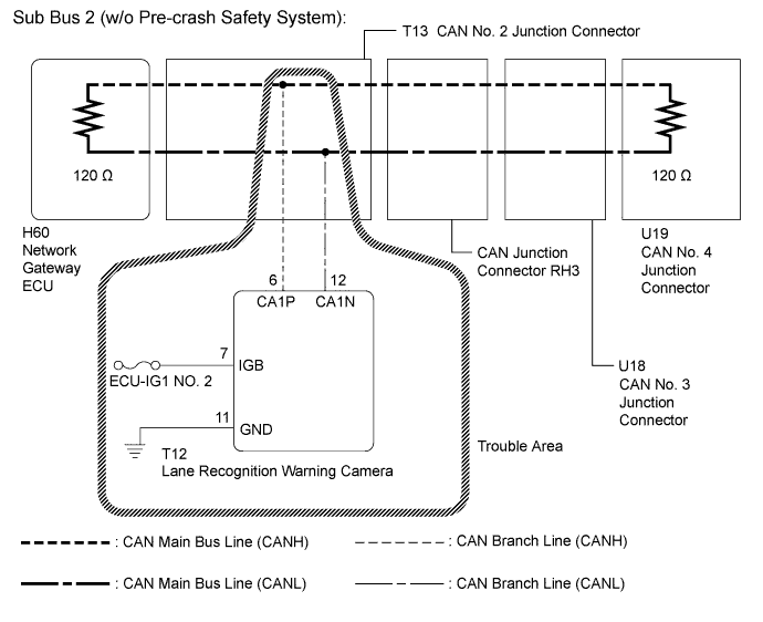
w/o Pre-crash safety system:
This diagnosis procedure is for when DTC U023A is output by the Gateway of the network gateway ECU (GTS display: Gateway).
-
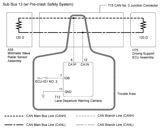
w/ Pre-crash safety system:
This diagnosis procedure is for when DTC U023A is output by the combination meter assembly (GTS display: Combination Meter).
WIRING DIAGRAM
INSPECTION PROCEDURE
Note
-
Before measuring the resistance of the CAN bus, turn the engine switch off and leave the vehicle for 1 minute or more without operating the key, switches or opening or closing the doors. After that, disconnect the cable from the negative (-) battery terminal and leave the vehicle for 1 minute or more before measuring the resistance.
-
After turning the engine switch off, waiting time may be required before disconnecting the cable from the negative (-) battery terminal. Therefore, make sure to read the disconnecting the cable from the negative (-) battery terminal notice before proceeding with work Click here.
-
Because the order of diagnosis is important to allow correct diagnosis, make sure to begin troubleshooting using How to Proceed with Troubleshooting when CAN communication system related DTCs are output Click here.
-
After performing repairs, perform the procedure listed in DTC Reproduction Method and confirm that the DTCs are not output again.
-
DTC check procedure: Turn the engine switch on (IG), wait at least 52 seconds and then drive the vehicle at a speed of 1 km/h (1 mph) or more for 7 seconds or more.
-
After the repair, perform CAN Bus Check and check that all the ECUs and sensors connected to the CAN communication system are displayed Click here.
Tech Tips
-
Operating the engine switch, any other switches or a door triggers related ECU and sensor communication on the CAN. This communication will cause the resistance value to change.
-
Even after DTCs are cleared, if a DTC is stored again after driving the vehicle for a while, the malfunction may be occurring due to vibration of the vehicle. In such a case, wiggling the ECUs or wire harness while performing the inspection below may help determine the cause of the malfunction.
-
When the vehicle is equipped with both the pre-crash safety system and lane departure alert system, if DTC U023A is output from the combination meter assembly (GTS display: Combination Meter), check that the V bus, sub bus 2 and sub bus 13 are normal by referring to How to Proceed with Troubleshooting before performing inspection for DTC U023A.
PROCEDURE
-
CHECK VEHICLE TYPE
-
Check vehicle type.
Result Result Proceed to w/o Pre-crash safety system A w/ Pre-crash safety system B
B 
CHECK FOR OPEN IN CAN BUS LINES (LANE DEPARTURE WARNING CAMERA BRANCH LINE) Click here
A 
-
-
RECONFIRM DTC OUTPUT
-
Reconfirm DTCs.
Tech Tips
If DTC U1002 is output from Gateway of the network gateway ECU, this indicates a sub bus 2 malfunction. Troubleshoot for DTC U1002 and check for malfunctions in sub bus 2.
Result Result Proceed to U1002 is not output from network gateway ECU
(GTS display: Gateway)
A U1002 is output from network gateway ECU
(GTS display: Gateway)
B
B 
GO TO DIAGNOSIS PROCEDURE INDICATED BY OUTPUT DTC Click here
A
-
-
CHECK FOR OPEN IN CAN BUS LINES (LANE DEPARTURE WARNING CAMERA BRANCH LINE)
-
Disconnect the cable from the negative (-) battery terminal.
-
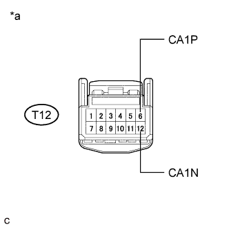
Text in Illustration *a Front view of wire harness connector
(to Lane Departure Warning Camera)
Disconnect the T12 lane departure warning camera connector.
-
Measure the resistance according to the value(s) in the table below.
Standard Resistance Tester Connection Condition Specified Condition T12-6 (CA1P) - T12-12 (CA1N) Cable disconnected from negative (-) battery terminal 54 to 69 Ω
NG
REPAIR OR REPLACE CAN BRANCH LINE OR CONNECTOR (LANE DEPARTURE WARNING CAMERA)
OK
-
-
CHECK HARNESS AND CONNECTOR (GROUND TERMINAL)
-
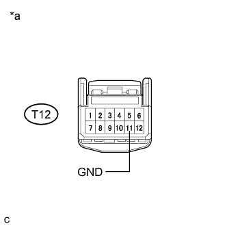
Text in Illustration *a Front view of wire harness connector
(to Lane Departure Warning Camera)
Measure the resistance according to the value(s) in the table below.
Standard Resistance Tester Connection Condition Specified Condition T12-11 (GND) - Body ground Cable disconnected from negative (-) battery terminal Below 1 Ω
NG
REPAIR OR REPLACE HARNESS OR CONNECTOR (GROUND CIRCUIT)
OK
-
-
CHECK HARNESS AND CONNECTOR (POWER SOURCE TERMINAL)
-
Connect the cable to the negative (-) battery terminal.
-
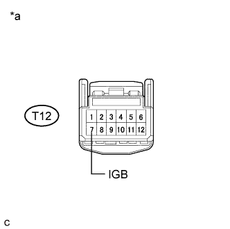
Text in Illustration *a Front view of wire harness connector
(to Lane Departure Warning Camera)
Measure the voltage according to the value(s) in the table below.
Standard Voltage Tester Connection Condition Specified Condition T12-7 (IGB) - Body ground Engine switch on (IG) 11 to 14 V
NG
REPAIR OR REPLACE HARNESS OR CONNECTOR (POWER SOURCE CIRCUIT)
OK 
REPLACE LANE DEPARTURE WARNING CAMERA Click here
-