LIN COMMUNICATION SYSTEM, Diagnostic DTC:B126A

| DTC Code | DTC Name |
|---|---|
| B126A | Remote Engine Starter ECU Communication Stop |
DESCRIPTION
The main body ECU (multiplex network body ECU) communicates with the accessory ECUs via BERKES communication.
These DTCs are stored when communication between the main body ECU (multiplex network body ECU) and accessory ECU stops for 10 seconds or more.
| DTC No. | DTC Detection Condition | Trouble Area |
|---|---|---|
| B126A | No communication between main body ECU (multiplex network body ECU) and accessory ECU for 10 seconds or more. |
|
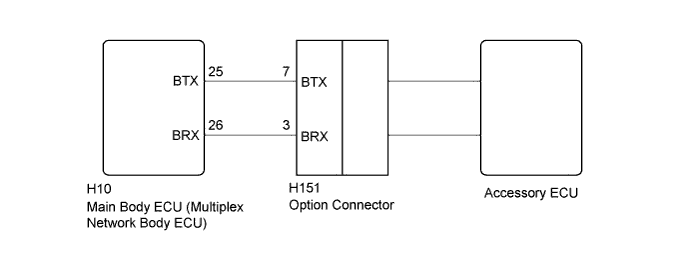
WIRING DIAGRAM
INSPECTION PROCEDURE
Note
-
Before starting repair, check that the power source system of the accessory ECU is not malfunctioning.
-
If the main body ECU (multiplex network body ECU) is replaced, refer to Service Bulletin.
PROCEDURE
-
CHECK HARNESS AND CONNECTOR MAIN BODY ECU (MULTIPLEX NETWORK BODY ECU) - OPTION CONNECTOR
-
Disconnect the H10 main body ECU (multiplex network body ECU) connector.
-
Disconnect the H151 option connector.
-
Measure the resistance according to the value(s) in the table below.
Standard Resistance Tester Connection Condition Specified Condition H10-25 (BTX) - H151-7 (BTX) Always Below 1 Ω H10-26 (BRX) - H151-3 (BRX) Always Below 1 Ω H10-26 (BRX) - Body ground Always 10 kΩ or higher H151-3 (BRX) - Body ground Always 10 kΩ or higher
NG 
REPAIR OR REPLACE HARNESS OR CONNECTOR
OK 
-
-
REPLACE OPTION CONNECTOR
-
Replace the option connector.
NEXT
-
-
CHECK DTC OUTPUT
-
Clear the DTCs Click here.
-
Recheck for DTCs.
OK DTC B126A and B1269 are not output.
NG
REPLACE MAIN BODY ECU (MULTIPLEX NETWORK BODY ECU) Click here
OK 
END (OPTION CONNECTOR ECU WAS DEFECTIVE)
-