CLEARANCE WARNING BUZZER INSTALLATION

-
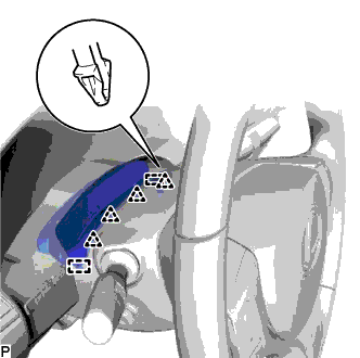
INSTALL NO. 1 CLEARANCE WARNING BUZZER
-
Engage the clamp to install the No. 1 clearance warning buzzer.
-
Connect the connector.
-
-
INSTALL RADIO RECEIVER ASSEMBLY WITH BRACKET (for Radio Receiver Type)
-
Connect each connector.
-
Engage the 2 clips and 2 claws to temporarily install the radio receiver assembly with bracket.
-
Install the radio receiver assembly with bracket with the 4 bolts.
-
-
INSTALL MULTI-MEDIA MODULE RECEIVER ASSEMBLY WITH BRACKET (for Multi-Media Module Receiver Type)
-
Connect each connector.
-
Engage the 2 clips and 2 claws to the vehicle body to temporarily install the multi-media module receiver assembly with bracket.
-
Install the multi-media module receiver assembly with bracket with the 4 bolts.
-
-
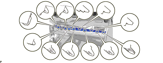
INSTALL LOWER CENTER INSTRUMENT PANEL FINISH PANEL
-
Engage the 2 claws and 5 clips to install the lower center instrument panel finish panel as shown in the illustration.
-
-
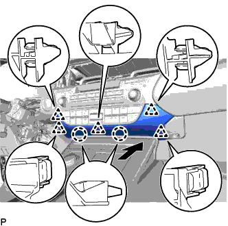
INSTALL NO. 2 INSTRUMENT PANEL REGISTER ASSEMBLY
-
Connect the connector.
-
Engage the 11 claws and clip to install the No. 2 instrument panel register assembly.
Note
When installing the No. 2 instrument panel register assembly, check that the wire harness is not caught between the No. 2 instrument panel register assembly and duct.
-
-
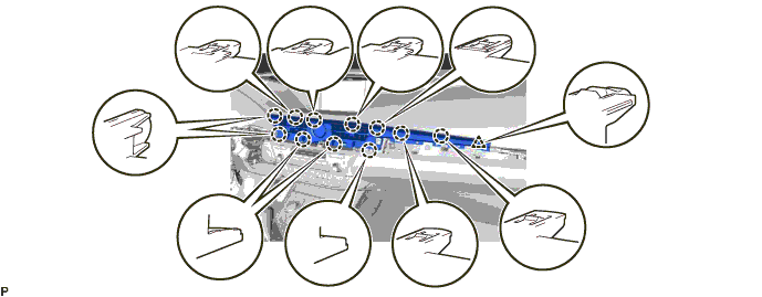
INSTALL CENTER INSTRUMENT CLUSTER FINISH PANEL GARNISH
-
Connect the connector.
-
Engage the 10 claws and 2 clips to install the center instrument cluster finish panel garnish.
-
-
INSTALL INSTRUMENT CLUSTER FINISH PANEL SUB-ASSEMBLY
-
Engage the 5 claws and 2 guides.
-
Install the 2 screws.
-
Engage the 4 clips and 2 guides to install the instrument cluster finish panel sub-assembly.
-
-
CONNECT CABLE TO NEGATIVE BATTERY TERMINAL (for Multi-Media Module Receiver Type)
Note
When disconnecting the cable, some systems need to be initialized after the cable is reconnected Click here.
-
CUSTOMIZE POWER TILT AND POWER TELESCOPIC STEERING COLUMN SYSTEM (for Power Tilt and Power Telescopic Steering Column)
Note
Reset the auto away/return function setting to the previous condition by changing the customize parameter Click here.