LEXUS PARKING ASSIST-SENSOR SYSTEM, Diagnostic DTC:C1AE9

| DTC Code | DTC Name |
|---|---|
| C1AE9 | Rear Right Sensor Malfunction |
DESCRIPTION
The No. 1 ultrasonic sensor (rear right sensor) is installed on the front bumper. The ECU detects obstacles based on signals received from the No. 1 ultrasonic sensor (rear right sensor). If the No. 1 ultrasonic sensor (rear right sensor) has an open circuit or other malfunction, it will not function normally.
| DTC No. | DTC Detection Condition | Trouble Area |
|---|---|---|
| C1AE9 | A malfunction of the No. 1 ultrasonic sensor (rear right sensor). |
|
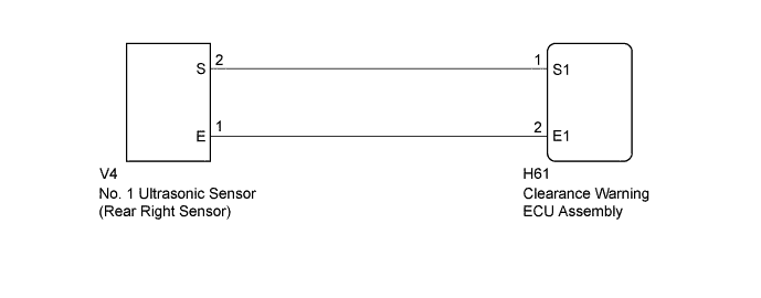
WIRING DIAGRAM
INSPECTION PROCEDURE
Note
If DTCs are output after repairs, turn the engine switch on (IG) and turn the clearance sonar main switch on. Then clear the DTCs Click here.
PROCEDURE
-
INSPECT NO. 1 ULTRASONIC SENSOR (REAR RIGHT SENSOR)
-
Remove the No. 1 ultrasonic sensor (rear right sensor) Click here.
-
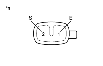
Text in Illustration *a Component without harness connected
(No. 1 Ultrasonic Sensor (Rear Right Sensor))
Measure the resistance according to the value(s) in the table below.
Standard Resistance Tester Connection Condition Specified Condition 2 (S) - 1 (E) Always 20 to 40 kΩ
NG 
REPLACE NO. 1 ULTRASONIC SENSOR (REAR RIGHT SENSOR) Click here
OK 
-
-
CHECK HARNESS AND CONNECTOR (NO. 1 ULTRASONIC SENSOR (REAR RIGHT SENSOR) - CLEARANCE WARNING ECU ASSEMBLY)
-
Disconnect the V4 No. 1 ultrasonic sensor (rear right sensor) connector.
-
Disconnect the H61 clearance warning ECU assembly connector.
-
Measure the resistance according to the value(s) in the table below.
Standard Resistance Tester Connection Condition Specified Condition V4-2 (S) - H61-1 (S1) Always Below 1 Ω V4-1 (E) - H61-2 (E1) Always Below 1 Ω V4-2 (S) - Body ground Always 10 kΩ or higher V4-1 (E) - Body ground Always 10 kΩ or higher Result Result Proceed to NG A OK (for LHD) B OK (for RHD) C
B
REPLACE CLEARANCE WARNING ECU ASSEMBLY Click here
C
REPLACE CLEARANCE WARNING ECU ASSEMBLY Click here
A 
REPAIR OR REPLACE HARNESS OR CONNECTOR
-