G-BOOK SYSTEM (w/ Telematics Transceiver) Received Voice Signal Circuit
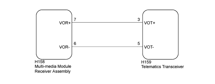
WIRING DIAGRAM
INSPECTION PROCEDURE
Note
Depending on the parts that are replaced during vehicle inspection or maintenance, performing initialization, registration or calibration may be needed. Refer to Precautions for G-BOOK Click here.
PROCEDURE
-
CHECK HARNESS AND CONNECTOR (MULTI-MEDIA MODULE RECEIVER ASSEMBLY - TELEMATICS TRANSCEIVER)
-
Disconnect the H158 multi-media module receiver assembly connector.
-
Disconnect the H159 telematics transceiver connector.
-
Measure the resistance according to the value(s) in the table below.
Standard Resistance Tester Connection Condition Specified Condition H158-7 (VOR+) - H159-3 (VOT+) Always Below 1 Ω H158-6 (VOR-) - H159-5 (VOT-) Always Below 1 Ω H158-7 (VOR+) - Body ground Always 10 kΩ or higher H158-6 (VOR-) - Body ground Always 10 kΩ or higher
NG 
REPAIR OR REPLACE HARNESS OR CONNECTOR
OK 
-
-
INSPECT TELEMATICS TRANSCEIVER
-
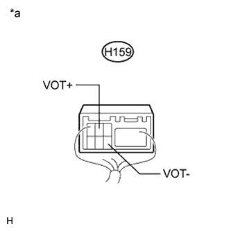
Text in Illustration *a Component with harness connected
(Telematics Transceiver)
Check for pulses according to the value(s) in the table below.
Standard Tester Connection Condition Specified Condition H159-3 (VOT+) - Body ground Receiving a call while using the operator service A waveform synchronized with the received voice is output. H159-5 (VOT-) - Body ground Receiving a call while using the operator service A waveform synchronized with the received voice is output.
NG
REPLACE TELEMATICS TRANSCEIVER Click here
OK 
REPLACE MULTI-MEDIA MODULE RECEIVER ASSEMBLY Click here
-