G-BOOK SYSTEM (w/ Telematics Transceiver), Diagnostic DTC:B15C6

| DTC Code | DTC Name |
|---|---|
| B15C6 | Ignition Switch Signal Malfunction |
DESCRIPTION
If vehicle movement (10 km/h (6 mph) or more for 10 seconds) is detected based on the location data sent from the multi-media module receiver assembly even when the telematics transceiver detects that the engine switch is off, this DTC will be stored.
| DTC No. | DTC Detection Condition | Trouble Area |
|---|---|---|
| B15C6 | IG signal error |
|
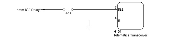
WIRING DIAGRAM
INSPECTION PROCEDURE
Note
-
Inspect the fuses for circuits related to this system before performing the following inspection procedure.
-
Depending on the parts that are replaced during vehicle inspection or maintenance, performing initialization, registration or calibration may be needed. Refer to Precautions for G-BOOK Click here.
PROCEDURE
-
CLEAR DTC
-
Clear the DTCs Click here.
NEXT 
-
-
CHECK DTC
-
Recheck for DTCs and check that no DTCs are output Click here.
OK No DTCs are output.
NG 
CHECK HARNESS AND CONNECTOR (TELEMATICS TRANSCEIVER - BATTERY, BODY GROUND) Click here
OK 
USE SIMULATION METHOD TO CHECK Click here
-
-
CHECK HARNESS AND CONNECTOR (TELEMATICS TRANSCEIVER - BATTERY, BODY GROUND)
-
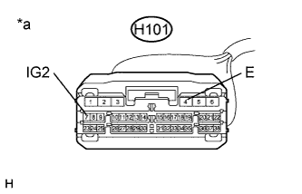
Text in Illustration *a Front view of wire harness connector
(to Telematics Transceiver)
Disconnect the H101 telematics transceiver connector.
-
Measure the resistance according to the value(s) in the table below .
Standard Resistance Tester Connection Condition Specified Condition H101-4 (E) - Body ground Always Below 1 Ω -
Measure the voltage according to the value(s) in the table below.
Standard Voltage Tester Connection Condition Specified Condition H101-7 (IG2) - Body ground Engine switch on (IG) 11 to 14 V
NG 
REPAIR OR REPLACE HARNESS OR CONNECTOR
OK
REPLACE TELEMATICS TRANSCEIVER Click here
-