G-BOOK SYSTEM (w/ Telematics Transceiver), Diagnostic DTC:B15C4

| DTC Code | DTC Name |
|---|---|
| B15C4 | Airbag Signal Malfunction/Not Input |
DESCRIPTION
If the telematics transceiver detects an error in communication between the telematics transceiver and the airbag sensor assembly as a result of the telematics transceiver self check, this DTC will be stored.
| DTC No. | DTC Detection Condition | Trouble Area |
|---|---|---|
| B15C4 | Airbag signal problem |
|
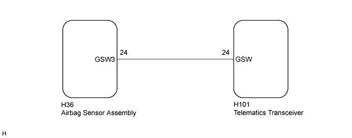
WIRING DIAGRAM
INSPECTION PROCEDURE
Note
Depending on the parts that are replaced during vehicle inspection or maintenance, performing initialization, registration or calibration may be needed. Refer to Precautions for G-BOOK Click here.
PROCEDURE
-
CHECK DTC (AIRBAG SYSTEM)
-
Clear the DTCs Click here.
-
Recheck for DTCs and check that no DTCs are output.
OK No DTCs are output.
NG 
GO TO AIRBAG SYSTEM Click here
OK 
-
-
CLEAR DTC
-
Clear the DTCs Click here.
NEXT
-
-
RECHECK DTC
-
Recheck for DTCs and check that no DTCs are output Click here.
OK No DTCs are output.
NG 
CHECK HARNESS AND CONNECTOR (TELEMATICS TRANSCEIVER - AIRBAG SENSOR ASSEMBLY) Click here
OK 
END
-
-
CHECK HARNESS AND CONNECTOR (TELEMATICS TRANSCEIVER - AIRBAG SENSOR ASSEMBLY)
-
Disconnect the H101 telematics transceiver connector.
-
Disconnect the H36 airbag sensor assembly connector.
-
Measure the resistance according to the value(s) in the table below.
Standard Resistance Tester Connection Condition Specified Condition H101-24 (GSW) - H36-24 (GSW3) Always Below 1 Ω H101-24 (GSW) - Body ground Always 10 kΩ or higher
NG
REPAIR OR REPLACE HARNESS OR CONNECTOR
OK
-
-
INSPECT TELEMATICS TRANSCEIVER
-
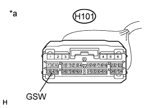
Disconnect the H101 telematics transceiver connector.
-
Text in Illustration *a Front view of wire harness connector
(to Telematics Transceiver)
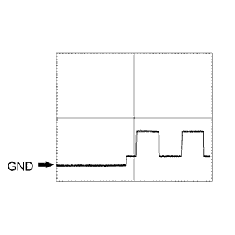
Check the input waveform.
-
Check the signal waveform according to the condition(s) in the table below. (Check the waveform from the back of the wire harness connector of the telematics transceiver while the airbag sensor assembly connectors are connected.)
Item Condition Tester Connection H101-24 (GSW) - Body ground Tool setting 5.0 V/DIV., 20 ms/DIV. Vehicle condition Engine switch on (IG) OK The waveform is output normally as shown in the illustration.
-
NG
REPLACE AIRBAG SENSOR ASSEMBLY Click here
OK
REPLACE TELEMATICS TRANSCEIVER Click here
-
-
REPLACE AIRBAG SENSOR ASSEMBLY
-
Replace the airbag sensor assembly with a known good one Click here.
NEXT
-
-
CLEAR DTC
-
Clear the DTCs Click here.
NEXT
-
-
RECHECK DTC
-
Recheck for DTCs and check that no DTCs are output Click here.
OK No DTCs are output.
NG
REPLACE TELEMATICS TRANSCEIVER Click here
OK
END (AIRBAG SENSOR ASSEMBLY WAS DEFECTIVE)
-