G-BOOK SYSTEM (w/ Telematics Transceiver), Diagnostic DTC:B15CC

| DTC Code | DTC Name |
|---|---|
| B15CC | Backup Battery Failure |
DESCRIPTION
If the telematics transceiver receives a defect, high temperature or low voltage signal from the mayday battery or does not receive any signals during mayday battery self-diagnosis, this DTC will be stored.
| DTC No. | DTC Detection Condition | Trouble Area |
|---|---|---|
| B15CC | Mayday battery malfunction |
|
WIRING DIAGRAM
INSPECTION PROCEDURE
Note
Depending on the parts that are replaced during vehicle inspection or maintenance, performing initialization, registration or calibration may be needed. Refer to Precautions for G-BOOK Click here.
PROCEDURE
-
CHECK DTC
-
Clear the DTCs Click here.
-
Recheck for DTCs and check that no DTCs are output.
OK No DTCs are output.
NG 
CHECK HARNESS AND CONNECTOR (TELEMATICS TRANSCEIVER - MAYDAY BATTERY) Click here
OK 
USE SIMULATION METHOD TO CHECK Click here
-
-
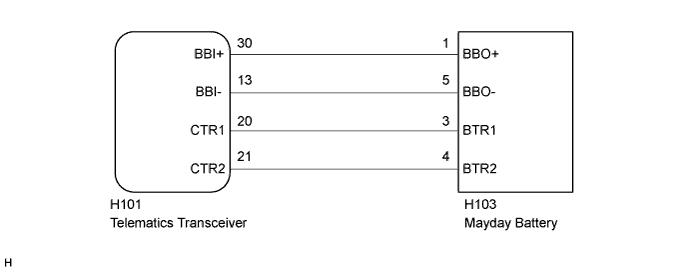
CHECK HARNESS AND CONNECTOR (TELEMATICS TRANSCEIVER - MAYDAY BATTERY)
-
Disconnect the H101 telematics transceiver connector.
-
Disconnect the H103 mayday battery connector.
-
Measure the resistance according to the value(s) in the table below.
Standard Resistance Tester Connection Condition Specified Condition H101-30 (BBI+) - H103-1 (BBO+) Always Below 1 Ω H101-13 (BBI-) - H103-5 (BBO-) Always Below 1 Ω H101-20 (CTR1) - H103-3 (BTR1) Always Below 1 Ω H101-21 (CTR2) - H103-4 (BTR2) Always Below 1 Ω H101-30 (BBI+) - Body ground Always 10 kΩ or higher H101-13 (BBI-) - Body ground Always 10 kΩ or higher H101-20 (CTR1) - Body ground Always 10 kΩ or higher H101-21 (CTR2) - Body ground Always 10 kΩ or higher
NG 
REPAIR OR REPLACE HARNESS OR CONNECTOR
OK 
-
-
REPLACE MAYDAY BATTERY
-
Replace the mayday battery with a known good one and check if the same DTC is output again Click here.
-
Clear the DTCs Click here.
-
Recheck for DTCs and check that no DTCs are output.
OK No DTCs are output.
-
NG
REPLACE TELEMATICS TRANSCEIVER Click here
OK
END (MAYDAY BATTERY WAS DEFECTIVE)
-