NAVIGATION RECEIVER REMOVAL

-
PRECAUTION
Note
After turning the engine switch off, waiting time may be required before disconnecting the cable from the negative (-) battery terminal. Therefore, make sure to read the disconnecting the cable from the negative (-) battery terminal notices before proceeding with work Click here.
Note
w/ G-BOOK System:When removing the hard disk drive, eliminate static electricity by touching the vehicle body to prevent components from being damaged.
-
CUSTOMIZE POWER TILT AND POWER TELESCOPIC STEERING COLUMN SYSTEM (for Power Tilt and Power Telescopic Steering Column)
-
Disable the auto away/return function by changing the customize parameter Click here.
Note
Record the current customize parameter setting (whether the auto away/return function is enabled or disabled) in order to restore the current setting after finishing this operation.
Tech Tips
Performing the above operation disables the auto away/return function when the engine switch is turned off.
-
Turn the engine switch on (IG). Operate the tilt and telescopic switch to fully extend and lower the steering column assembly.
-
Turn the engine switch off.
-
-
DISCONNECT CABLE FROM NEGATIVE BATTERY TERMINAL
Note
When disconnecting the cable, some systems need to be initialized after the cable is reconnected Click here.
-
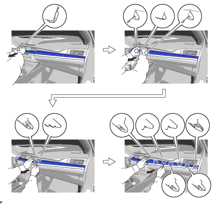
REMOVE INSTRUMENT CLUSTER FINISH PANEL SUB-ASSEMBLY
-
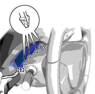
Using a moulding remover, disengage the 4 clips and 2 guides.
-
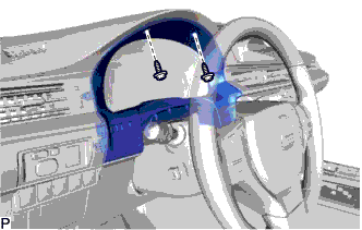
Remove the 2 screws.
-
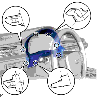
Disengage the 5 claws and 2 guides and remove the instrument cluster finish panel sub-assembly.
-
-
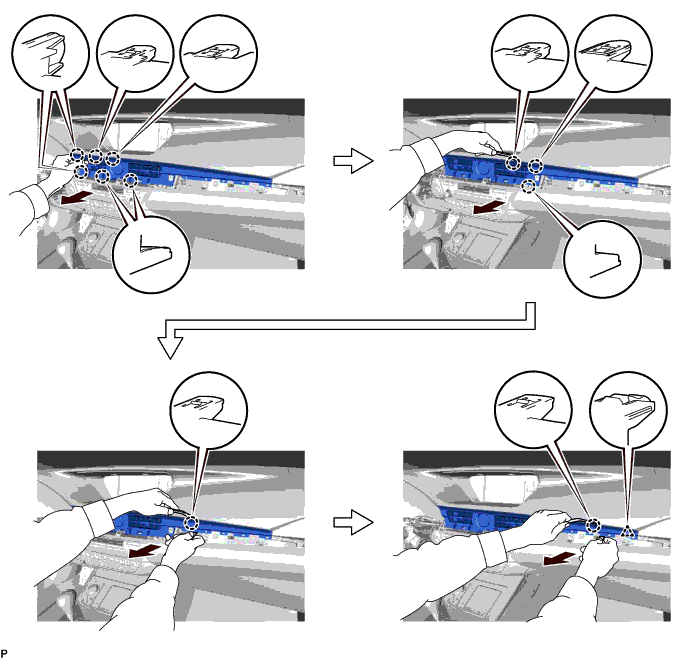
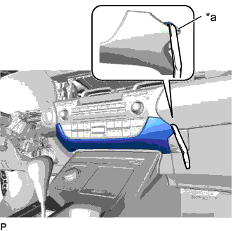
REMOVE CENTER INSTRUMENT CLUSTER FINISH PANEL GARNISH
-
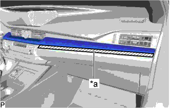
Text in Illustration *a Protective Tape Apply protective tape to the area shown in the illustration.
-
Using a moulding remover, disengage the 10 claws and 2 clips as shown in the illustration.
-
Disconnect the connector to remove the center instrument cluster finish panel garnish.
-
-
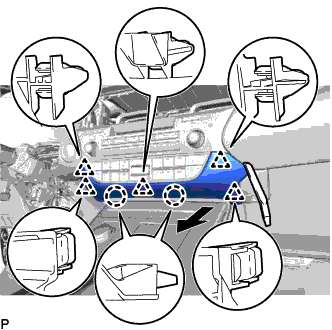
REMOVE NO. 2 INSTRUMENT PANEL REGISTER ASSEMBLY
-
Using a moulding remover, disengage the 11 claws and clip as shown in the illustration.
-
Disconnect the connector to remove the No. 2 instrument panel register assembly.
-
-
REMOVE LOWER CENTER INSTRUMENT PANEL FINISH PANEL
-
Text in Illustration *a Lower Center Instrument Panel Finish Panel Hole Insert a moulding remover as shown in the illustration.
-
Using a moulding remover, disengage the 2 claws and 5 clips and remove the lower center instrument panel finish panel as shown in the illustration.
-
-
REMOVE MULTI-MEDIA MODULE RECEIVER ASSEMBLY WITH BRACKET
-
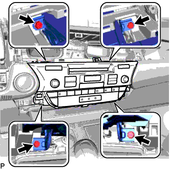
Remove the 4 bolts.
-
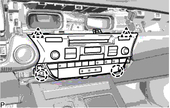
Pull the multi-media module receiver assembly with bracket toward the rear of the vehicle and disengage the 2 clips and 2 claws.
-
Disconnect each connector and remove the multi-media module receiver assembly with bracket.
-
-
REMOVE NO. 1 RADIO BRACKET
-
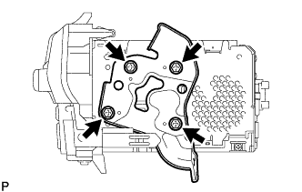
Remove the 4 screws and No. 1 radio bracket.
-
-
REMOVE NO. 2 RADIO BRACKET
-
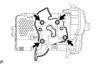
Remove the 4 screws and No. 2 radio bracket.
-
-
REMOVE HARD DISK DRIVE (w/ G-BOOK System)
-
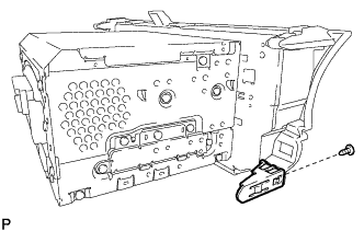
Remove the screw and claw.
-
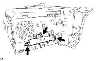
Remove the 3 screws and cover.
-
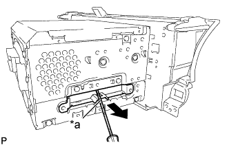
Text in Illustration *a Protective Tape Using a screwdriver with its tip wrapped with protective tape, slide the hard disk drive in the direction shown by the arrow to remove it.
-
-
REMOVE MULTI-MEDIA MODULE RECEIVER ASSEMBLY