WINDSHIELD DEICER SYSTEM Windshield Deicer does not Operate
DESCRIPTION
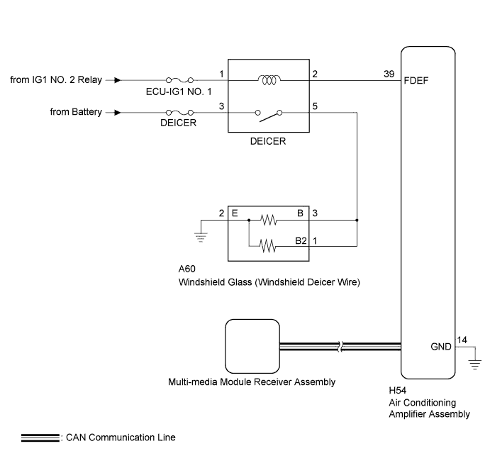
When the windshield deicer switch is operated, the operation signal is transmitted to the multi-media module receiver assembly. The multi-media module receiver assembly transmits the operation signal to the air conditioning amplifier assembly via CAN communication. When the air conditioning amplifier assembly receives the signal, it turns on the DEICER relay to operate the windshield deicer.
WIRING DIAGRAM
INSPECTION PROCEDURE
Note
-
Inspect the fuses for circuits related to this system before performing the following inspection procedure.
-
The windshield deicer system uses CAN communication. First, confirm that there are no malfunctions in the communication lines. Refer to How to Proceed with Troubleshooting Click here.
-
If the battery voltage becomes low, windshield deicer system operation is canceled to prioritize supplying power to the power steering system.
PROCEDURE
-
CHECK AIR CONDITIONING SYSTEM
-
Check that the air conditioning system can be operated using the remote touch.
Tech Tips
Both the windshield deicer system operation signal and air conditioning system operation signal are transmitted to the air conditioning amplifier assembly through same communication line.
OK The air conditioning system operates normally.
NG 
GO TO AIR CONDITIONING SYSTEM Click here
OK 
-
-
PERFORM ACTIVE TEST USING GTS
-
Connect the GTS to the DLC3.
-
Turn the engine switch on (IG).
-
Turn the GTS on.
-
Enter the following menus: Body Electrical / Air Conditioner / Active Test.
-
Perform the Active Test according to the display on the GTS.
Air Conditioner Tester Display Test Part Control Range Diagnostic Note Deicer Relay (Front) Windshield deicer OFF or ON - OK The windshield deicer system operates normally.
NG 
INSPECT DEICER RELAY Click here
OK
-
-
REPLACE AIR CONDITIONING AMPLIFIER ASSEMBLY
-
Replace the air conditioning amplifier assembly with a new or known good one Click here.
-
Check that the windshield deicer system operates normally.
OK The windshield deicer system operates normally.
NG
REPLACE MULTI-MEDIA MODULE RECEIVER ASSEMBLY Click here
OK 
END (AIR CONDITIONING AMPLIFIER ASSEMBLY WAS DEFECTIVE)
-
-
INSPECT DEICER RELAY
-
Inspect the deicer relay Click here.
NG
REPLACE DEICER RELAY
OK
-
-
CHECK HARNESS AND CONNECTOR (DEICER RELAY - IG1 NO. 2 RELAY AND BATTERY)
-
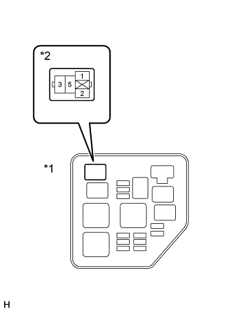
Text in Illustration *1 NO. 2 Engine Room Relay Block Assembly *2 Deicer Relay Holder Remove the deicer relay from the NO. 2 engine room relay block assembly.
-
Measure the voltage according to the value(s) in the table below.
Standard Voltage Tester Connection Condition Specified Condition Deicer relay holder terminal-1 - Body ground Engine switch on (IG) 11 to 14 V Deicer relay holder terminal-3 - Body ground Always 11 to 14 V
NG
REPAIR OR REPLACE HARNESS OR CONNECTOR
OK
-
-
CHECK HARNESS AND CONNECTOR (DEICER RELAY - AIR CONDITIONING AMPLIFIER ASSEMBLY)
-
Text in Illustration *1 NO. 2 Engine Room Relay Block Assembly *2 Deicer Relay Holder Disconnect the H54 air conditioning amplifier assembly connector.
-
Measure the resistance according to the value(s) in the table below.
Standard Resistance Tester Connection Condition Specified Condition Deicer relay holder terminal-2 - H54-39 (FDEF) Always Below 1 Ω Deicer relay holder terminal-2 - Body ground Always 10 kΩ or higher
NG
REPAIR OR REPLACE HARNESS OR CONNECTOR
OK
-
-
CHECK AIR CONDITIONING AMPLIFIER ASSEMBLY
-
Reconnect the H54 air conditioning amplifier assembly connector.
-
Reinstall the deicer relay.
-
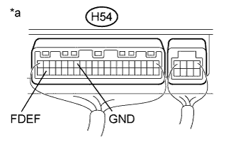
Text in Illustration *a Component with harness connected
(Air Conditioning Amplifier Assembly)
Remove the air conditioning amplifier assembly with its connectors still connected Click here.
-
Measure the voltage according to the value(s) in the table below.
Standard Voltage Tester Connection Condition Specified Condition H54-39 (FDEF) - H54-14 (GND) Engine switch on (IG)
Deicer switch ON
Below 2.2 V H54-39 (FDEF) - H54-14 (GND) Engine switch on (IG)
Deicer switch OFF
11 to 14 V
NG
REPLACE AIR CONDITIONING AMPLIFIER ASSEMBLY Click here
OK
-
-
CHECK HARNESS AND CONNECTOR (WINDSHIELD GLASS (WINDSHIELD DEICER WIRE) - DEICER RELAY AND BODY GROUND)
-
Text in Illustration *1 NO. 2 Engine Room Relay Block Assembly *2 Deicer Relay Holder Disconnect the A60 windshield glass (windshield deicer wire) connector.
-
Remove the deicer relay from the NO. 2 engine room relay block assembly.
-
Measure the resistance according to the value(s) in the table below.
Standard Resistance Tester Connection Condition Specified Condition A60-3 (B) - Deicer relay holder terminal-5 Always Below 1 Ω A60-1 (B2) - Deicer relay holder terminal-5 Always Below 1 Ω A60-3 (B) - Body ground Always 10 kΩ or higher A60-1 (B2) - Body ground Always 10 kΩ or higher A60-2 (E) - Body ground Always Below 1 Ω
NG
REPAIR OR REPLACE HARNESS OR CONNECTOR
OK
REPLACE WINDSHIELD GLASS (WINDSHIELD DEICER WIRE) Click here
-