WINDSHIELD GLASS INSTALLATION

Note
When replacing the windshield glass of a vehicle equipped with a lane departure warning camera, make sure to use a Lexus genuine part. The lane departure warning camera may not be able to be installed due to a missing bracket or the lane departure alert system may not operate properly due to a difference in the transmissivity or black ceramic border.
-
INSTALL NO. 1 WINDSHIELD GLASS STOPPER (for 2-piece Type)
-
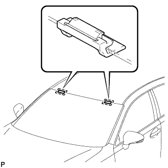
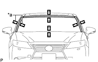
Install 2 new No. 1 windshield glass stoppers to the vehicle body as shown in the illustration.
Tech Tips
Only 2-piece type windshield glass stoppers are provided as supply parts. Use 2-piece type stoppers as replacements even if 1-piece type stoppers were originally installed.
-
-
INSTALL NO. 2 WINDSHIELD GLASS STOPPER (for 2-piece Type)
-
Using a brush or sponge, coat the application area of 2 new No. 2 windshield glass stoppers with primer G.
Note
-
Do not apply too much primer G.
-
Allow the primer G to dry for 3 minutes or more.
-
Throw away any leftover primer G.
Tech Tips
If an area other than specified is coated by accident, wipe off the primer G with a clean piece of cloth before it dries.
-
-
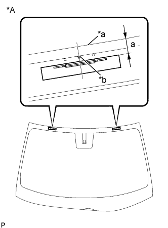
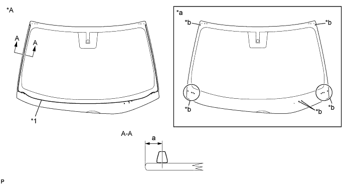
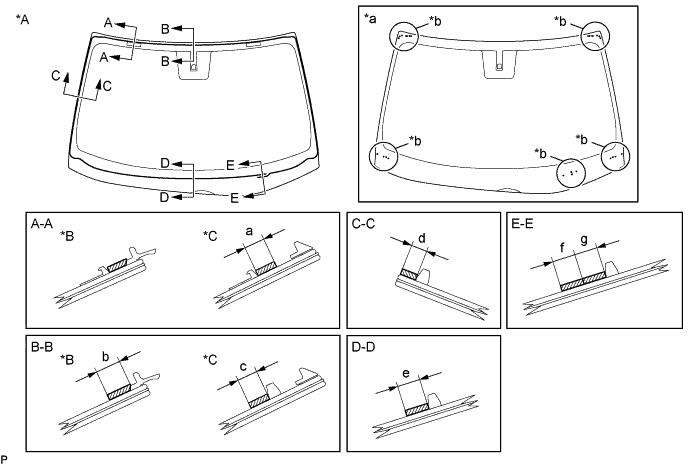
Text in Illustration *A Back Side *a Windshield Glass Edge Side *b Ceramic Notch Install the 2 new No. 2 windshield glass stoppers to the windshield glass as shown in the illustration.
Standard Dimension Area Dimension a for Standard 13.6 to 14.6 mm (0.535 to 0.575 in.) for Glass Roof 25.7 to 26.7 mm (1.01 to 1.05 in.) Tech Tips
Only 2-piece type windshield glass stoppers are provided as supply parts. Use the 2-piece type stoppers as replacements even if 1-piece type stoppers were originally installed.
-
-
INSTALL WINDSHIELD GLASS RETAINER
-
Using a brush or sponge, coat the application area of 2 new windshield glass retainers with primer G.
Note
-
Do not apply too much primer G.
-
Allow the primer G to dry for 3 minutes or more.
-
Throw away any leftover primer G.
Tech Tips
If an area other than specified is coated by accident, wipe off the primer G with a clean piece of cloth before it dries.
-
-
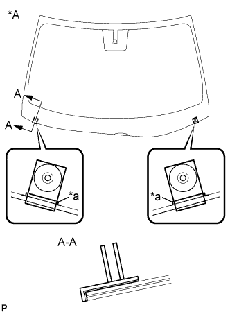
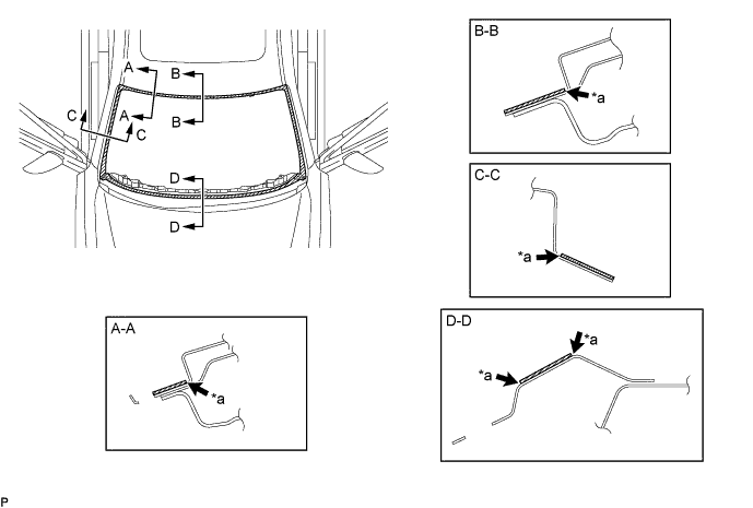
Text in Illustration *A Back Side *a Ceramic Notch Install the 2 new windshield glass retainers onto the windshield glass as shown in the illustration.
-
-
INSTALL WINDSHIELD OUTSIDE MOULDING
-
Using a brush or sponge, coat the application area of a new windshield outside moulding with primer G.
Note
-
Do not apply too much primer G.
-
Allow the primer G to dry for 3 minutes or more.
-
Throw away any leftover primer G.
Tech Tips
If an area other than specified is coated by accident, wipe off the primer G with a clean piece of cloth before it dries.
-
-
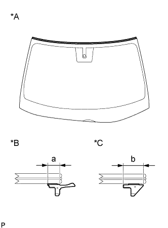
Text in Illustration *A Back Side *B for Standard *C for Glass Roof Install the new windshield outside moulding onto the windshield glass as shown in the illustration.
Standard Dimension Area Dimension a 6.65 mm (0.262 in.) b 10.0 mm (0.394 in.) Note
-
Do not apply too much primer G.
-
Allow the primer G to dry for 3 minutes or more.
-
Throw away any leftover primer G.
Tech Tips
If an area other than specified is coated by accident, wipe off the primer G with a clean piece of cloth before it dries.
-
-
-
INSTALL WINDSHIELD GLASS ADHESIVE DAM
-
Using a brush or sponge, coat the application area of a new windshield glass adhesive dam with primer G.
Note
-
Do not apply too much primer G.
-
Allow the primer G to dry for 3 minutes or more.
-
Throw away any leftover primer G.
Tech Tips
If an area other than specified is coated by accident, wipe off the primer G with a clean piece of cloth before it dries.
-
-
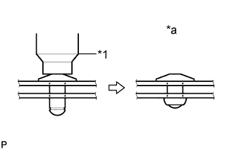
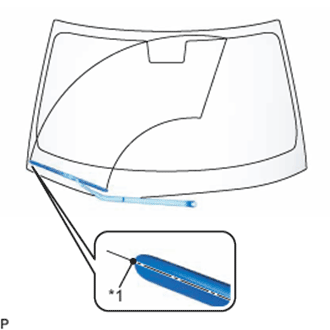
Install the windshield glass adhesive dam onto the windshield glass as shown in the illustration.
Text in Illustration *A Back Side - - *1 Windshield Glass Adhesive Dam - - *a Ceramic Notch Position *b Ceramic Notch Standard Dimension Area Dimension a 9.6 mm (0.378 in.)
-
-
INSTALL WINDSHIELD GLASS ADHESIVE DAM (for Glass Roof)
-
Using a brush or sponge, coat the application area of a new windshield glass adhesive dam with primer G.
Note
-
Do not apply too much primer G.
-
Allow the primer G to dry for 3 minutes or more.
-
Throw away any leftover primer G.
Tech Tips
If an area other than specified is coated by accident, wipe off the primer G with a clean piece of cloth before it dries.
-
-
Install the windshield glass adhesive dam onto the windshield glass as shown in the illustration.
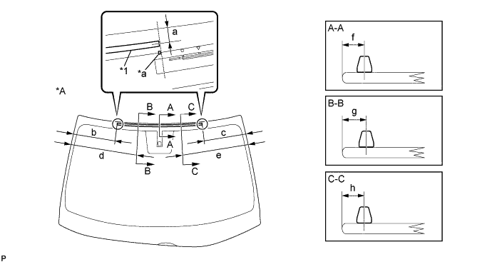
Text in Illustration *A Back Side - - *1 Windshield Glass Adhesive Dam - - *a Ceramic Notch - - Standard Dimension Area Dimension a 16.4 mm (0.646 in.) b 292.1 mm (11.5 in.) c 292.1 mm (11.5 in.) d 450 mm (1.476 ft.) e 450 mm (1.476 ft.) f 20.3 mm (0.799 in.) g 19.4 mm (0.764 in.) h 19.4 mm (0.764 in.)
-
-
INSTALL NO. 1 WINDSHIELD OUTSIDE MOULDING CLIP LH
-

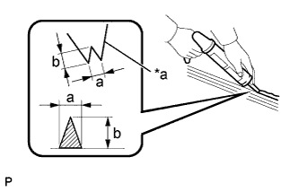
Using an air riveter or a hand riveter with a nose piece, install the 5 windshield No. 1 outside moulding clips with 5 new rivets.
Tech Tips
If the mandrel of the rivet does not come off on the first operation of the rivet gun, slide the rivet gun forward on the mandrel and operate it again.
Note
-
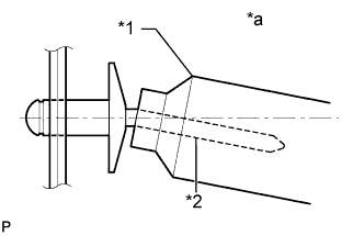
Do not pry the rivet with the riveter, as this will cause damage to the riveter and mandrel.
Text in Illustration *1 Riveter *2 Mandrel *a Incorrect -
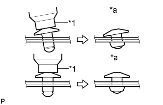
Confirm that the rivets are seated properly against the roof drip side finish moulding clip.
Text in Illustration *1 Riveter *a Incorrect -
Do not tilt the riveter when installing the rivet to the roof drip side finish moulding clip.
-
Do not leave any clearance between the rivet head and roof drip side finish moulding clip.
-
Do not leave any clearance between the roof drip side finish moulding clip and front pillar. Firmly hold the 2 items together while installing the rivet.
Text in Illustration *1 Riveter *a Incorrect
-
-
-
INSTALL NO. 1 WINDSHIELD OUTSIDE MOULDING CLIP RH
Tech Tips
Use the same procedure as for the LH side.
-
INSTALL WINDSHIELD GLASS SUB-ASSEMBLY (for LHD)
-
Text in Illustration *a Matchmark Position the windshield glass sub-assembly.
-
Using suction cups, place the windshield glass sub-assembly in the correct position.
-
Check that the whole contact surface of the windshield glass sub-assembly rim is perfectly even.
-
Align the matchmarks on the windshield glass sub-assembly and vehicle body.
Note
Check that the No. 1 and No. 2 windshield glass stoppers are installed to the vehicle body correctly.
-
Remove the windshield glass sub-assembly.
-
-
Using a brush, coat the installation surface on the vehicle body with primer M.
Text in Illustration *a Edge of Curved Surface - - 
Primer M - - Note
-
Do not coat the adhesive with primer M.
-
Do not apply too much primer M.
-
Allow the primer M to dry for 3 minutes or more.
-
Throw away any leftover primer M.
Tech Tips
If an area other than specified is coated by accident, wipe off the primer M with a clean piece of cloth before it dries.
-
-
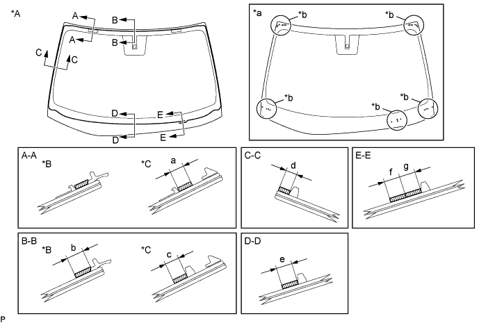
Using a brush or sponge, coat the application area of adhesive with primer G.
Text in Illustration *A Back Side *B for Standard *C for Glass Roof - - *a Ceramic Notch Position *b Ceramic Notch Primer G - - Standard Dimension Area Dimension a 8.0 mm (0.315 in.) or more b 11.0 mm (0.433 in.) or more c 11.0 mm (0.433 in.) or more d 7.0 mm (0.276 in.) or more e 11.0 mm (0.433 in.) or more f 11.0 mm (0.433 in.) or more g 11.0 mm (0.433 in.) or more Note
-
Do not apply too much primer G.
-
Allow the primer G to dry for 3 minutes or more.
-
Throw away any leftover primer G.
Tech Tips
-
Apply primer G onto the ceramic notches.
-
If an area other than specified is coated by accident, wipe off the primer G with a clean piece of cloth before it dries.
-
-
Apply adhesive to the windshield glass sub-assembly.
Adhesive Toyota Genuine Windshield Glass Adhesive or equivalent
-
Text in Illustration *a Nozzle Cut off the tip of the cartridge nozzle as shown in the illustration.
Standard Dimension Area Dimension a 8.0 mm (0.315 in.) or more b 12.0 mm (0.472 in.) or more Tech Tips
After cutting off the tip, use all adhesive within the time described in the table below.
Usage Time Frame Temperature Usage Time Frame 35°C (95°F) 15 minutes 20°C (68°F) 1 hour and 40 minutes 5°C (41°F) 8 hours -
Load the sealer gun with the cartridge.
-
Apply adhesive to the windshield glass sub-assembly as shown in the illustration.
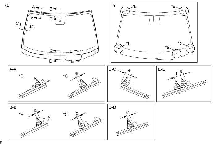
Text in Illustration *A Back Side *B for Standard *C for Glass Roof - - *a Ceramic Notch Position *b Ceramic Notch Adhesive - - Standard Dimension Area Dimension a 4.0 mm (0.157 in.) b 4.0 mm (0.157 in.) c 4.0 mm (0.157 in.) d 7.0 mm (0.276 in.) or more e 4.0 mm (0.157 in.) f 8.0 mm (0.315 in.) g 4.0 mm (0.157 in.) Tech Tips
Apply adhesive onto the ceramic notches.
-
-
Text in Illustration *a Matchmark Install the windshield glass sub-assembly.
-
Using suction cups, position the windshield glass sub-assembly so that the matchmarks are aligned, and press it in gently along the rim.
Note
-
Check that the No. 1 and No. 2 windshield glass stoppers are installed to the vehicle body correctly.
-
Check the clearance between the vehicle body and windshield glass sub-assembly.
-
-
Lightly press the front surface of the windshield glass sub-assembly to ensure that the windshield glass is securely fit to the vehicle body.
Tech Tips
Press the glass with a force of 98 N (10 kgf, 22.0 lbf) or more.
-
Using a scraper, remove any excess or protruding adhesive.
-
Hold the windshield glass using protective tape until the applied adhesive becomes hard.
Note
Do not drive the vehicle for the time described in the table below.
Minimum Time Temperature Minimum Time prior to Driving Vehicle 35°C (95°F) 1 hour and 30 minutes 20°C (68°F) 5 hours 5°C (41°F) 24 hours
-
-
w/ Windshield Deicer System:
-
Connect the connector.
-
-
-
INSTALL WINDSHIELD GLASS SUB-ASSEMBLY (for RHD)
-
Text in Illustration *a Matchmark Position the windshield glass sub-assembly.
-
Using suction cups, place the windshield glass sub-assembly in the correct position.
-
Check that the whole contact surface of the windshield glass sub-assembly rim is perfectly even.
-
Align the matchmarks on the windshield glass sub-assembly and vehicle body.
Note
Check that the No. 1 and No. 2 windshield glass stoppers are installed to the vehicle body correctly.
-
Remove the windshield glass sub-assembly.
-
-
Using a brush, coat the installation surface on the vehicle body with primer M.
Text in Illustration *a Edge of Curved Surface - - Primer M - - Note
-
Do not coat the adhesive with primer M.
-
Do not apply too much primer M.
-
Allow the primer M to dry for 3 minutes or more.
-
Throw away any leftover primer M.
Tech Tips
If an area other than specified is coated by accident, wipe off the primer M with a clean piece of cloth before it dries.
-
-
Using a brush or sponge, coat the application area of adhesive with primer G.
Text in Illustration *A Back Side *B for Standard *C for Glass Roof - - *a Ceramic Notch Position *b Ceramic Notch Primer G - - Standard Dimension Area Dimension a 8.0 mm (0.315 in.) or more b 11.0 mm (0.433 in.) or more c 11.0 mm (0.433 in.) or more d 7.0 mm (0.276 in.) or more e 11.0 mm (0.433 in.) or more f 11.0 mm (0.433 in.) or more g 11.0 mm (0.433 in.) or more Note
-
Do not apply too much primer G.
-
Allow the primer G to dry for 3 minutes or more.
-
Throw away any leftover primer G.
Tech Tips
-
Apply primer G onto the ceramic notches.
-
If an area other than specified is coated by accident, wipe off the primer G with a clean piece of cloth before it dries.
-
-
Apply adhesive to the windshield glass sub-assembly.
Adhesive Toyota Genuine Windshield Glass Adhesive or equivalent
-
Text in Illustration *a Nozzle Cut off the tip of the cartridge nozzle as shown in the illustration.
Standard Dimension Area Dimension a 8.0 mm (0.315 in.) or more b 12.0 mm (0.472 in.) or more Tech Tips
After cutting off the tip, use all adhesive within the time described in the table below.
Usage Time Frame Temperature Usage Time Frame 35°C (95°F) 15 minutes 20°C (68°F) 1 hour and 40 minutes 5°C (41°F) 8 hours -
Load the sealer gun with the cartridge.
-
Apply adhesive to the windshield glass sub-assembly as shown in the illustration.

Text in Illustration *A Back Side *B for Standard *C for Glass Roof - - *a Ceramic Notch Position *b Ceramic Notch Adhesive - - Standard Dimension Area Dimension a 4.0 mm (0.157 in.) b 4.0 mm (0.157 in.) c 4.0 mm (0.157 in.) d 7.0 mm (0.276 in.) or more e 4.0 mm (0.157 in.) f 8.0 mm (0.315 in.) g 4.0 mm (0.157 in.) Tech Tips
Apply adhesive onto the ceramic notches.
-
-
Text in Illustration *a Matchmark Install the windshield glass sub-assembly.
-
Using suction cups, position the windshield glass sub-assembly so that the matchmarks are aligned, and press it in gently along the rim.
Note
-
Check that the No. 1 and No. 2 windshield glass stoppers are installed to the vehicle body correctly.
-
Check the clearance between the vehicle body and windshield glass sub-assembly.
-
-
Lightly press the front surface of the windshield glass sub-assembly to ensure that the windshield glass is securely fit to the vehicle body.
Tech Tips
Press the glass with a force of 98 N (10 kgf, 22.0 lbf) or more.
-
Using a scraper, remove any excess or protruding adhesive.
-
Hold the windshield glass using protective tape until the applied adhesive becomes hard.
Note
Do not drive the vehicle for the time described in the table below.
Minimum Time Temperature Minimum Time prior to Driving Vehicle 35°C (95°F) 1 hour and 30 minutes 20°C (68°F) 5 hours 5°C (41°F) 24 hours
-
-
-
INSPECT FOR LEAK
-
After the adhesive has hardened, apply water from the outside of the vehicle. Check that no water leaks into the cabin.
-
If water leaks into the cabin, allow the water to dry and add adhesive.
-
Remove the protective tape.
-
-
INSTALL ROOF HEADLINING ASSEMBLY
-
INSTALL INNER REAR VIEW MIRROR ASSEMBLY
-
INSTALL LANE DEPARTURE WARNING CAMERA (w/ Lane Departure Alert System)
-
INSTALL RAIN SENSOR (w/ Rain Sensor)
-
INSTALL WINDSHIELD OUTSIDE MOULDING LH
-
Engage the guide and 10 claws to install the windshield outside moulding.
-
-
INSTALL WINDSHIELD OUTSIDE MOULDING RH
Tech Tips
Use the same procedure as for the LH side.
-
INSTALL COWL TOP VENTILATOR LOUVER SUB-ASSEMBLY
-
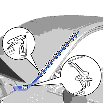
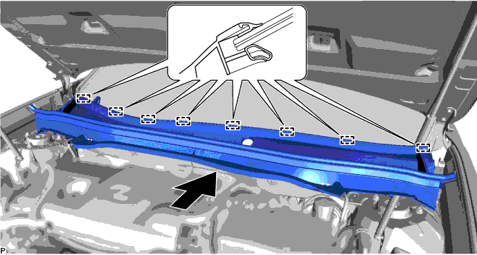
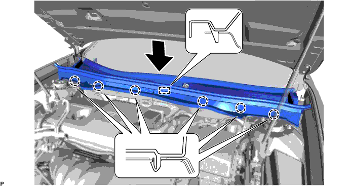
Engage the 8 guides as shown in the illustration.
-
Engage the 6 claws and guide to install the cowl top ventilator louver sub-assembly.
-
Engage the claw and connect the windshield outside moulding LH.
-
Engage the claw and connect the windshield outside moulding RH.
-
-
INSTALL FRONT WIPER ARM AND BLADE ASSEMBLY LH
-
When reusing the front wiper arm and blade assembly LH:
-
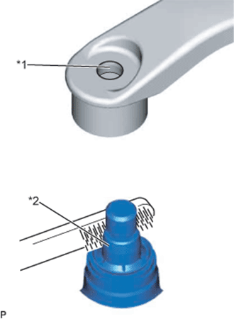
Text in Illustration *1 Wiper Arm Serration *2 Wiper Pivot Serration Clean the wiper arm serrations to remove any burrs, dirt, etc.
Note
Do not grind down the wiper arm serrations.
-
-
When reusing the windshield wiper link assembly:
-
Clean the wiper pivot serrations with a wire brush.
-
-
Operate the wiper and stop the windshield wiper motor assembly at the automatic stop position.
-
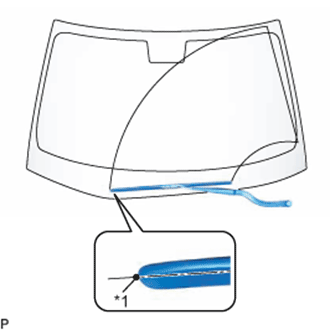
Text in Illustration *1 Ceramic Dot Install the front wiper arm and blade assembly LH with the nut to the position shown in the illustration.
- Torque:
- 22 N*m { 224 kgf*cm, 16 ft.*lbf }
Tech Tips
Hold the wiper arm by hand while tightening the nut.
-
-
INSTALL FRONT WIPER ARM AND BLADE ASSEMBLY RH
-
When reusing the front wiper arm and blade assembly RH:
-

Text in Illustration *1 Wiper Arm Serration *2 Wiper Pivot Serration Clean the wiper arm serrations to remove any burrs, dirt, etc.
Note
Do not grind down the wiper arm serrations.
-
-
When reusing the windshield wiper link assembly:
-
Clean the wiper pivot serrations with a wire brush.
-
-
Operate the wiper and stop the windshield wiper motor assembly at the automatic stop position.
-
Text in Illustration *1 Ceramic Dot Install the front wiper arm and blade assembly RH with the nut to the position shown in the illustration.
- Torque:
- 22 N*m { 224 kgf*cm, 16 ft.*lbf }
Tech Tips
Hold the wiper arm by hand while tightening the nut.
-
Turn the engine switch on (IG).
-
Operate the front wiper while spraying washer fluid onto the windshield glass. Make sure that the front wiper functions properly and the wiper does not come into contact with the vehicle body.
-
Lift each wiper arm twice after the wipers stop and check the wiper set position.
-
Turn the engine switch off.
-