NAVIGATION SYSTEM SYSTEM DESCRIPTION

-
NAVIGATION SYSTEM OUTLINE
-
Vehicle position tracking methods
It is essential that the navigation system correctly tracks the current vehicle position and displays it on the map. There are 2 methods to track the current vehicle position: autonomous (dead reckoning) and GPS* (satellite) navigation. Both navigation methods are used in conjunction with each other.
*: GPS (Global Positioning System)
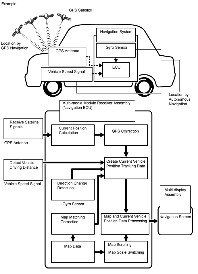
Operation Description Vehicle Position Calculation The multi-media module receiver assembly calculates the current vehicle position (direction and current position) using the direction deviation signal from the gyro sensor and driving distance signal from the vehicle speed sensor and creates the driving route. Map Display Processing The multi-media module receiver assembly processes the vehicle position data, vehicle driving track and map data from the hard disk drive. Map Matching The map data from the hard disk drive is compared to the vehicle position and driving track data. Then, the vehicle position is matched with the nearest road. GPS Correction The vehicle position is matched to the position measured by the GPS. Then, the GPS measurement position data is compared with the vehicle position and driving track data. If the position is very different, the GPS measurement position is used. Distance Correction The vehicle speed signal includes the error caused by tire wear and slippage between the tires and road surface. Distance correction is performed to account for this. The multi-media module receiver assembly automatically offsets the signal to make up for the difference between it and the distance data of the map. The offset is automatically updated. 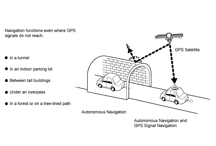
Tech Tips
The combination of autonomous and GPS navigation makes it possible to display the vehicle position even when the vehicle is in places where GPS signals cannot be received. When only autonomous navigation is used, however, the mapping accuracy may slightly decrease.
-
Autonomous navigation
This method determines the relative vehicle position based on the driving track determined by the gyro located in the multi-media module receiver assembly and the vehicle speed signal.
-
Gyro sensor
Used to calculate the direction by detecting angular velocity. It is located in the multi-media module receiver assembly.
-
Vehicle speed signal
Used to calculate the vehicle driving distance.
-
-
GPS*navigation (Satellite navigation)
This method detects the absolute vehicle position using radio waves from GPS satellites.
*: GPS satellites were launched by the U.S. Department of Defense for military purposes.
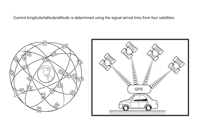
Number of Satellites Measurement Description 2 or less Measurement is impossible Vehicle position cannot be obtained because the number of satellites is not enough. 3 2-dimensional measurement is possible Vehicle position is obtained based on the current longitude and latitude. (This is less precise than 3-dimensional measurement.) 4 3-dimensional measurement is possible Vehicle position is obtained based on the current longitude, latitude and altitude. -
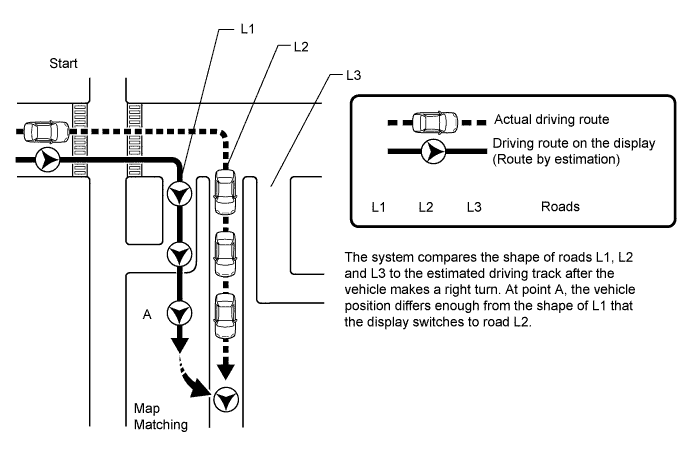
Map matching
The current driving route is calculated by autonomous navigation (according to the gyro sensor and vehicle speed signal) and GPS navigation. This information is then compared with possible road shapes from the map data in the hard disk drive and the vehicle position is set onto the most appropriate road.
-
-
REMOTE TOUCH OUTLINE
Tech Tips
-
The navigation system is remotely controlled using the remote touch switch knob and switches.
-
The remote touch is equipped with a feedback force function.
-
When the remote touch switch knob is operated, the built-in 2-axis motors are controlled. The motors are used to provide feedback force for the knob according to the pointer operation displayed on the multi-display assembly.
-
The feedback force of the remote touch allows the users to select icons easily when operating the navigation system.
-
Remote Touch Switch Knob Operation
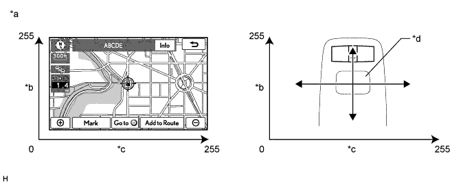
Text in Illustration *a Example *b Longitudinal Axis *c Lateral Axis *d Switch Knob
-
Movement of the pointer on the multi-display assembly screen is synchronized with knob operation.
Tech Tips
-
During remote touch switch knob operation, the distance that the knob moves is sent to the multi-media module receiver assembly as operational coordinates. The range of operational coordinates for the lateral and longitudinal axes is between 0 and 255.
-
The multi-display assembly also has operational coordinates that range from 0 to 255 for the lateral and longitudinal axes. The multi-media module receiver assembly displays the pointer according to the operational coordinates from the knob.
-
-
-
Remote Touch Switch Knob Feedback Force
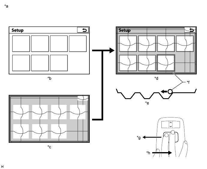
Text in Illustration *a Example *b Display *c Feedback Force Image Screen *d Screen Image *e Feedback Force Image *f Pointer *g Movement Direction *h Feedback Force (When Providing Resistance)
-
The remote touch has 2 built-in motors. These motors control both lateral and longitudinal axes and generate feedback force according to remote touch switch knob operation.
Tech Tips
-
There are 3 types of feedback force image areas (icons, frames and others) provided on the multi-display assembly screen. The feedback force changes depending on the area.
-
The multi-media module receiver assembly sends a feedback force request signal to the remote touch according to the pointer location displayed on the multi-display assembly.
-
When the remote touch receives the feedback force request signal, the remote touch controls the motors and generates 3 types of feedback force according to the operation direction of the remote touch switch knob.
-
The strength of feedback force generated by the remote touch can be adjusted. Refer to the owner's manual for further information.
-
-
Icon Area
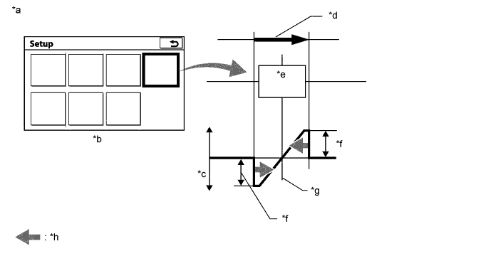
Text in Illustration *a Example *b Display *c Generated Feedback Force *d Switch Knob Operation *e Icon *f Force to Pull Pointer to Center of Icon *g Center of Icon *h Feedback Force Tech Tips
-
When the pointer comes close to an icon area, force will be provided to pull the pointer toward the center of the icon area.
-
Stronger force is provided while driving than while parked.
-
-
Frame Area
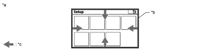
Text in Illustration *a Example *b Frame Area *c Feedback Force - - Tech Tips
Frame areas are provided for the edges of all display screens. When the pointer comes close to the edge of the screen, force will be provided to move the pointer away from the edge of the screen.
-
Other Area
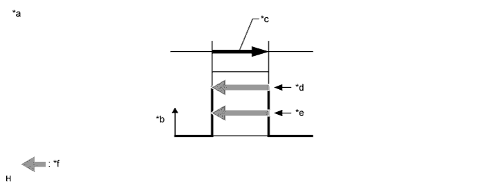
Text in Illustration *a Example *b Generated Feedback Force *c Switch Knob Operation (User Input) *d Fast Knob Operation (Strong Feedback) *e Slow Knob Operation (Weaker Feedback) *f Feedback Force Tech Tips
-
When the pointer is in an area other than one of those specified, resistance will be provided that is proportional to the remote touch switch knob operation speed.
-
Stronger resistance is provided on the map screen than on other screens.
-
-
-
-
DVD (Digital Versatile Disc) PLAYER OUTLINE
-
The DVD player can only play DVD videos that have any of the following marks:

-
The following products may not be playable on your player.
-
Video CD
-
DVD+R
-
DVD+RW
-
DVD-RAM
-
-
Precaution for use of discs
Note
-
PAL or SECAM color television standard discs cannot be played (only NTSC disc can be played).
-
Keep the discs away from dirt. Be careful not to damage the discs or leave fingerprints on them.
-
Hold discs by the outer edge and center hole with the label side up.
-
Leaving the disc exposed halfway out of the slot for a long time after pressing the disc eject button may cause deformation of the disc, making the disc unusable.
-
Do not use odd-shaped discs because these may cause player malfunctions.
-
Do not use discs whose recording portion is transparent or translucent because they may not be inserted, ejected or played normally.
-
DualDiscs that mate DVD recorded material on one side with CD digital audio material on the other cannot be played.
-
-
-
CD (Compact Disc) PLAYER OUTLINE
-
A compact disc player uses a laser pickup to read digital signals recorded on a compact disc (CD). By converting the digital signals to analog, it can play music and audio.
CAUTION:
Do not look directly at the laser pickup because the CD player uses an invisible laser beam. Be sure to operate the player only as instructed.
Note
-
Do not disassemble any part of the CD player.
-
Do not apply oil to the CD player.
-
Do not insert anything but a CD into the CD player.
-
-
Usable discs
-
This player can play only audio CDs, CD-Rs (CD-Recordable) and CD-RWs (CD-ReWritable) that have any of the following marks:
-
-
Precautions for use of discs
Note
-
Copy-protected CDs cannot be played.
-
CD-Rs and CD-RWs may not be played depending on the recording conditions or characteristics of the discs, or due to damage, dirt or deterioration caused by leaving the discs in the cabin for a long time.
-
Unfinalized CD-Rs and CD-RWs cannot be played.
-
DualDiscs that mate DVD recorded material on one side with CD digital audio material on the other cannot be played.
-
Keep the discs away from dirt. Be careful not to damage the discs or leave fingerprints on them.
-
Hold discs by the outer edge and center hole with the label side up.
-
Leaving the disc exposed halfway out of the slot for a long time after pressing the disc eject button may cause deformation of the disc, making the disc unusable.
-
If discs have adhesive tape, stickers, CD labels or any traces of such labels attached, the discs may not be ejected or player malfunctions may result.
-
Keep the discs away from direct sunlight. (Exposure to direct sunlight may cause deformation of the disc, making the disc unusable.)
-
Do not use odd-shaped CDs because these may cause player malfunctions.
-
Do not use discs whose recording portion is transparent or translucent because they may not be inserted, ejected or played normally.
-
Use only 4.7 in. (12 cm) CDs.
-
Do not use 3 in. (8 cm) CDs either with or without adaptors.
Tech Tips
-
When it is cold or it is raining, if the windows mist up, mist and condensation may form in the player. In such cases, the CD may skip or stop in the middle of play. Ventilate or dehumidify the cabin for a while before using the player.
-
The CD may skip if the player experiences strong vibrations when the vehicle is driven on rough roads or similar uneven surfaces.
-
-
Cleaning
Note
Do not use a lens cleaner because it may cause a malfunction in the pickup portion of the player.
-
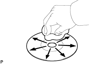
If dirt is on the disc surface, wipe it clean with a soft dry cloth such as an eyeglass cleaner for plastic lenses from the inside to the outside in a radial direction.
Note
-
Pressing on the disc by hand or rubbing the disc with a hard cloth may scratch the disc surface.
-
Use of solvents such as record spray, antistatic agents, alcohol, benzine, thinners or a chemical cloth may cause damage to the disc, making the disc unusable.
-
-
-
-
MP3/WMA OUTLINE
-
Playable MP3 file standards
Compatible standard MP3 (MPEG1 LAYER3, MPEG2 LSF LAYER3) Compatible sampling frequency
-
MPEG1 LAYER3: 32, 44.1, 48 (kHz)
-
MPEG2 LSF LAYER3: 16, 22.05, 24 (kHz)
Compatible bit rate
-
MPEG1 LAYER3: 32 to 320 (kbps)
-
MPEG2 LSF LAYER3: 8 to 160 (kbps)
-
Compatible with VBR
Compatible channel mode Stereo, joint stereo, dual channel, monaural -
-
Playable WMA file standards
Compatible standard WMA Ver. 7, 8, 9 Compatible sampling frequency 32, 44.1, 48 (kHz) Compatible bit rate (Only compatible with 2-channel playback)
-
Ver. 7, 8: CBR48 to 192 (kbps)
-
Ver. 9: CBR48 to 320 (kbps)
-
-
ID3 tag and WMA tag
-
Additional text information called an ID3 tag can be input to MP3 files. Information such as song titles and artist names can be stored.
Tech Tips
This player is compatible with ID3 tags of ID3 Ver. 1.0 and 1.1, and ID3 Ver. 2.2 and 2.3. (Number of characters complies with ID3 Ver. 1.0 and 1.1.)
-
Additional text information called a WMA tag can be input to WMA files. Information such as song titles and artist names can be stored.
-
-
Usable media
-
Only CD-ROMs, CD-Rs (CD-Recordable) and CD-RWs (CD-ReWritable) can be used to play MP3/WMA files.
Note
-
CD-Rs and CD-RWs are more easily affected by a hot and humid environment than discs used for normal audio CDs. For this reason, some CD-Rs and CD-RWs do not play.
-
If there are fingerprints or scratches on a disc, the disc may not play or the CD may skip.
-
Some CD-Rs and CD-RWs may deteriorate if they are left in the cabin for a long time.
-
Keep CD-Rs and CD-RWs in an opaque case.
-
-
-
Usable media format
-
Usable media format
Disc format CD-ROM Mode 1, CD-ROM XA Mode 2 Form 1 File format ISO9660 Level 1 and Level 2 (Joliet, Romeo) Tech Tips
-
As for MP3/WMA files written in any unlisted format, the contents of the files may not be played normally or the file names or folder names may not be displayed correctly.
-
This player is compatible with multi-session discs and can play CD-Rs and CD-RWs on which MP3/WMA files have been added. However, only the first session can be played.
-
Discs whose first session includes both music data and MP3 or WMA format data cannot be played.
-
-
Standards and restrictions
Maximum directory levels 8 levels Maximum number of characters for a folder name/file name 32 characters Maximum number of folders 192 (Including empty folders, route folders, and folders that do not contain MP3/WMA files) Maximum number of files in a disc 255 (Including non-MP3/WMA files)
-
-
File names
-
Only files with an extension of ".mp3" or ".wma" can be recognized and played as MP3 or WMA files.
-
Save MP3 or WMA files with an extension of ".mp3" or ".wma".
Note
If non-MP3 or non-WMA files are saved with an extension of ".mp3" or ".wma", those files may be wrongly recognized as MP3 or WMA files and played. A loud noise may occur and damage to the speakers may result.
-
-
-
"Bluetooth" OUTLINE
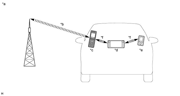
Text in Illustration *a Example *b Cellular Network *c Cellular Phone
("Bluetooth" compatible type)
*d Multi-media Module Receiver Assembly
(Built-in "Bluetooth" receiver antenna)
*e Portable Audio Player
("Bluetooth" compatible type)
*f "Bluetooth" Wireless Connection
-
"Bluetooth" is a trademark owned by Bluetooth SIG, Inc.
-
"Bluetooth" is a wireless connection technology that uses the 2.4 GHz frequency band.
Tech Tips
The communication performance of "Bluetooth" may vary depending on obstructions or radio wave conditions between communication devices, electromagnetic radiation, communication device sensitivity or antenna capacity.
-
Hands-free function
-
The "Bluetooth" built-in multi-media module receiver assembly and a "Bluetooth" compatible cellular phone*1 can be connected using a "Bluetooth" wireless connection. This enables the use of the hands-free function on the cellular phone even if the phone is in a pocket or bag. For this reason, it is not necessary to use a connector or cable to connect the cellular phone.
*1: Some versions of "Bluetooth" compatible cellular phones may not function.
-
Compatible hands-free devices
Required "Bluetooth" specifications Ver. 1.1 or higher (Ver. 2.1+EDR or higher recommended) Compatible profiles
-
HFP (Hands Free Profile) Ver.1.0 or higher (Ver.1.5 or higher recommended)*1
-
OPP (Object Push Profile) Ver.1.1 or higher*1
-
PBAP (Phone Book Access Profile) Ver.1.0 or higher*1
-
MAP (Message Access Profile) Ver.1.0 or higher*2
-
DUN (Dial-Up Networking Profile) Ver.1.1 or higher*3
Maximum number of hands-free devices that can be registered (including audio devices) 5
-
*1: This profile is necessary when using the handsfree function.
-
*2: This profile is necessary when using the message function. (w/ Connected Services)
-
*3: This profile is necessary when using the connected services. (w/ Connected Services)
Tech Tips
The amount of remaining battery charge displayed on the multi-media module receiver assembly may be different from that of the "Bluetooth" device.
-
-
-
"Bluetooth" audio function
-
The "Bluetooth" built-in multi-media module receiver assembly and a "Bluetooth" compatible portable audio player*2 can be connected using a "Bluetooth" wireless connection. This enables files stored in the portable audio player to be heard from the vehicle speakers. In addition, operations such as play/stop can be performed directly from the multi-media module receiver assembly.
*2: Some versions of "Bluetooth" compatible audio players may not be able to operate the "Bluetooth" function, or music may play, but functions available using the multi-media module receiver assembly may be limited.
-
Compatible "Bluetooth" audio devices
Required "Bluetooth" specifications Ver. 1.1 or higher (Ver. 2.1+EDR or higher recommended) Compatible profiles
-
A2DP (Advanced Audio Distribution Profile) Ver. 1.0 or higher (Ver. 1.2 or higher recommended)
-
AVRCP (Audio/Video Remote Control Profile) Ver. 1.0 or higher (Ver. 1.4 or higher recommended)
Maximum number of audio devices that can be registered (including hands-free devices) 5 Tech Tips
The amount of remaining battery charge displayed on the multi-media module receiver assembly may be different from that of the "Bluetooth" device.
-
-
-
-
RADIO DESCRIPTION
-
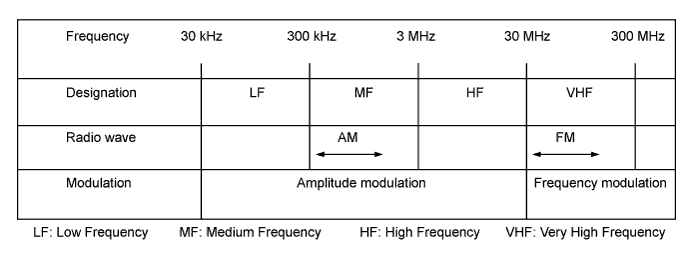
Radio frequency band
-
Radio broadcasts use the radio frequency bands shown in the table below.
-
-
Service area
-
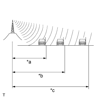
Text in Illustration *a FM (Stereo) *b FM (Monaural) *c AM The service areas of AM and FM broadcasts are vastly different. Sometimes an AM broadcast can be received very clearly but an FM stereo broadcast cannot. FM stereo has the smallest service area, and is prone to pick up static and other types of interference such as noise.
-
-
Radio reception problems
Tech Tips
In addition to static, other problems such as "phasing", "multipath" and "fade out" exist. These problems are not caused by electrical noise, but by the radio signal propagation method itself.
-
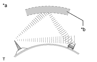
Text in Illustration *a Phasing *b Ionosphere Phasing
AM broadcasts are susceptible to electrical interference and another kind of interference called phasing. Occurring only at night, phasing is the interference created when a vehicle receives 2 radio wave signals from the same transmitter. One signal is reflected off the ionosphere and the other signal is received directly from the transmitter.
-
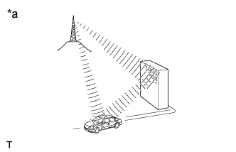
Text in Illustration *a Multipath Multipath
Multipath is a type of interference created when a vehicle receives 2 radio wave signals from the same transmitter. One signal is reflected off buildings or mountains and the other signal is received directly from the transmitter.
-
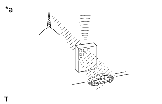
Text in Illustration *a Fade Out Fade out
Fade out is caused by objects (buildings, mountains and other such large obstacles) that deflect away part of a signal, resulting in a weaker signal when the object is between the transmitter and vehicle. High frequency radio waves, such as FM broadcasts, are easily deflected by obstructions. Low frequency radio waves, such as AM broadcasts, are less likely to deflect.
-
-
Noise problem
Technicians must have a clear understanding about each customer's noise complaint. Use the following table to diagnose noise problems.
Radio Frequency Noise Occurrence Condition Presumable Cause AM Noise occurs in a specific area Foreign noise Noise occurs when listening to an intermittent broadcast An identical program transmitted from multiple towers can cause noise where the signals overlap Noise occurs only at night Signal phasing FM Noise occurs while driving in a specified area Multipath resulting from a change in FM frequency
-
-
CONNECTED SERVICES OUTLINE (w/ Connected Services)
-
The following services are available by connecting the navigation system to Toyota's portal site via the internet using a cellular phone.
-
Online search: New establishments, such as restaurants, bars etc., that are not registered in the navigation system can be set as a destination.
-
Importing memory points: Establishments that were searched using a personal computer can be set as a destination and can be registered as memory points.
Tech Tips
-
For known compatible phones refer to www.my.toyota.eu.
-
It is necessary to agree to the terms of service for the search engine on www.my.toyota.eu.
Failure to do so may cause problems such as the search engine cannot be selected and the screen does not transfer to the next screen even when "Online search" is selected.
-
If the cellular phone has not been registered as a registered device, the "Communication settings" screen button cannot be selected.
-
Connected services are available only on a multi-media module receiver assembly that has had its identification code registered when the account was created.
-
Search results may not be displayed if the target establishment is not in the data supplied by the provider or in the map data of the navigation system.
-
As the information for a destination set using the connected services is supplied by the provider, the navigation system may guide to a location that deviates from the actual destination.
-
-
-
VEHICLE CUSTOMIZATION OUTLINE
-
Customization of functions can be performed on the multi-display assembly screen. Refer to the owner's manual for further information on customizable items for the navigation system.
Tech Tips
-
Items available for customization via the navigation system can be performed by using the GTS.
-
Some customize parameters displayed on the GTS will be displayed on the "Vehicle Customization" screen for the navigation system. Users can customize these items.
-
-
-
EXPORT / IMPORT MEMORY POINT FUNCTION OUTLINE
-
This function allows memory points stored in the multi-media module receiver assembly to be registered to another multi-media module receiver assembly.
Memory points stored in the multi-media module receiver assembly can be exported to a USB device.
Data exported to a USB device can be imported to another multi-media module receiver assembly using a USB device.
-
-
RDS-TMC FUNCTION OUTLINE (w/ RDS-TMC Function)
-
This system has a function which allows the reception of traffic information from Radio Data System Traffic Message Channel (RDS-TMC) stations based on FM-multiple broadcasting.
It assists the driver to avoid areas with traffic congestion. It also helps to improve traffic flow and road safety.
-
RDS-TMC Function List
-
Traffic information
Using RDS-TMC station based on FM-multiple broadcasting that is received, traffic events near the current position or the cursor position can be viewed as a list.
-
-
-
-
SOUND LIBRARY FUNCTION OUTLINE (w/ Sound Library Function)
-
Approximately 3000 tracks with a 5-minute track length average can be recorded to the HDD from audio discs using AAC encoding at 128 kbps (a maximum of 9999 tracks can be recorded if tracks with an average track length of less than 5 minutes are recorded or the tracks are encoded at less than 128 kbps).
-
Album, artist, genre and title names for recorded tracks can be input or edited freely.
-
These names make it possible to search for a track easily.
Tech Tips
-
Recording equipment should be used only for lawful copying. It is necessary to carefully confirm what is lawful copying in the country in which you are making a copy.
-
Copying of copyright material such as films or music is unlawful unless permitted by a legal exception or consent granted by the owners of the rights to the content.
-
-
-
USB AUDIO SYSTEM FUNCTION OUTLINE
-
The No. 1 stereo jack adapter assembly is equipped with a USB terminal. Connecting a USB device or "iPod" to the No. 1 stereo jack adapter assembly allows music files to be played. Not only is it possible to play music from a USB device with audio functions, is also possible to play MP3 or WMA music files that are stored on a USB device. In addition, "iPod" control software is installed, allowing file selection from playlists and operation using shuffle mode.
Tech Tips
Operation through the controls of a USB device or "iPod" cannot be performed while it is connected.
-
USB audio system compatible model
-
USB device
The following device formats can be used:
Compatible USB device formats
-
USB communication format: USB 2.0 HS (480Mbps) and FS (12Mbps)
-
File format: FAT16/32 (Windows)
-
Class: Mass storage class
MP3 and WMA files written in any format other than those listed above may not play correctly, and their names and folder names may not be displayed correctly.
Items related to standards and limitations are as follows:
-
Maximum directory hierarchy: 8 levels
-
Maximum number of folders in device: 3000 (including the root folder)
-
Maximum number of files in device: 9999
-
Maximum number of files per folder: 255
-
-
"iPod"
"iPhone", "iPod", "iPod classic", "iPod nano" and "iPod touch" are trademarks of Apple Inc., registered in the U.S. and other countries.
The following "iPod", "iPod nano", "iPod classic", "iPod touch" and "iPhone" devices can be used with this system.
Made for
-
"iPod touch" (4th generation)
-
"iPod touch" (3rd generation)
-
"iPod touch" (2nd generation)
-
"iPod touch" (1st generation)
-
"iPod classic"
-
"iPod with video"
-
"iPod nano" (6th generation)
-
"iPod nano" (5th generation)
-
"iPod nano" (4th generation)
-
"iPod nano" (3rd generation)
-
"iPod nano" (2nd generation)
-
"iPod nano" (1st generation)
-
"iPhone 4"
-
"iPhone 3GS"
-
"iPhone 3G"
-
"iPhone"
Tech Tips
Depending on differences between models or software versions etc., some models might be incompatible with this system.
-
-
-
-
CUSTOMIZE STARTUP IMAGE OR SCREEN OFF IMAGE FUNCTION OUTLINE
-
An image can be copied from a USB device. The image can be used as the startup image or screen off image of the navigation system.
-
-
AUTOMATIC SOUND LEVELIZER (ASL) FUNCTION OUTLINE
-
The Automatic Sound Levelizer (ASL) function automatically adjusts the audio system volume level in order to compensate for increased vehicle noise (vehicle noise tends to increase as vehicle speed increases). The ASL adjusts the volume level based upon vehicle speed signals that it receives from the combination meter assembly.
-
-
COMMUNICATION SYSTEM
-
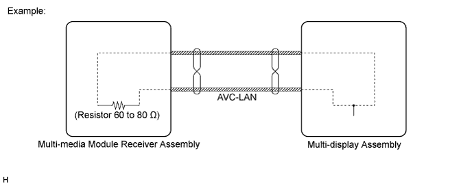
AVC-LAN Outline
-
Components of the navigation system communicate with each other via the AVC-LAN.
-
The AVC-LAN uses a twisted pair of wires for its communication lines.
-
The master unit of the AVC-LAN is the multi-media module receiver assembly.
Tech Tips
-
The multi-media module receiver assembly has the resistance (60 to 80 Ω) necessary for communication.
-
If a short or open circuit occurs in the AVC-LAN circuit, communication is interrupted and the system will not operate normally.
-
-
-
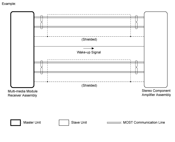
MOST Network Outline
-
Navigation system components communicate with each other via the MOST network.
-
The MOST network uses a shielded twisted pair of wires for its communication lines.
-
The master unit of the MOST network is the multi-media module receiver assembly.
-
MOST communication lines connect each slave unit centering around the master unit to form a MOST network ring.
-
The master unit sends a wake-up signal to activate each slave unit connected to the MOST network.
Tech Tips
If a short or open circuit occurs in the MOST network, communication will be interrupted and the system will not operate normally.
-
-
CAN Communication Outline
-
The navigation system uses CAN communication between the multi-media module receiver assembly and ECUs.
-
-
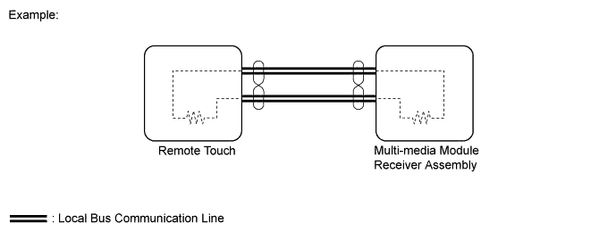
Local Bus Communication Outline
-
Components of the navigation system communicate with each other via the local bus.
-
The local bus uses a twisted pair of wires for its communication lines.
-
The master unit of the local bus is the multi-media module receiver assembly.
Tech Tips
-
The multi-media module receiver assembly has the resistance (108 to 132 Ω) necessary for communication.
-
The remote touch has the resistance (108 to 132 Ω) necessary for communication.
-
If a short or open circuit occurs in the local bus circuit, communication is interrupted and the system will not operate normally.
-
-
-
-
DIAGNOSTIC FUNCTION OUTLINE
-
The navigation system has a diagnostic function (the result is indicated on the master unit).
-