RADIO ANTENNA CORD INSTALLATION

-
INSTALL NO. 3 ANTENNA CORD SUB-ASSEMBLY (for LH Side with Digital Audio Broadcasting Antenna)
-
for Standard:
-
Engage the 4 clamps.
-
Install the No. 3 antenna cord sub-assembly with the bolt.
-
Connect the 2 connectors.
-
-
for Glass Roof:
-
Engage the 5 clamps.
-
Install the No. 3 antenna cord sub-assembly with the bolt.
-
Connect the 2 connectors.
-
-
-
INSTALL NO. 3 ANTENNA CORD SUB-ASSEMBLY (for RH Side with Digital Audio Broadcasting Antenna)
-
for Standard:
-
Engage the 5 clamps to install the No. 3 antenna cord sub-assembly.
-
Connect the connector.
-
-
for Glass Roof:
-
Engage the 4 clamps to install the No. 3 antenna cord sub-assembly.
-
Connect the connector.
-
-
-
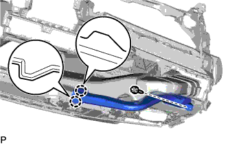
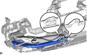
INSTALL NO. 3 ANTENNA CORD SUB-ASSEMBLY (w/ Roof Antenna)
-
Engage the 5 clamps to install the No. 3 antenna cord sub-assembly.
-
Connect the connector.
-
-
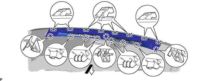
INSTALL NO. 2 ANTENNA CORD SUB-ASSEMBLY
-
Apply double-sided tape as shown in the illustration.
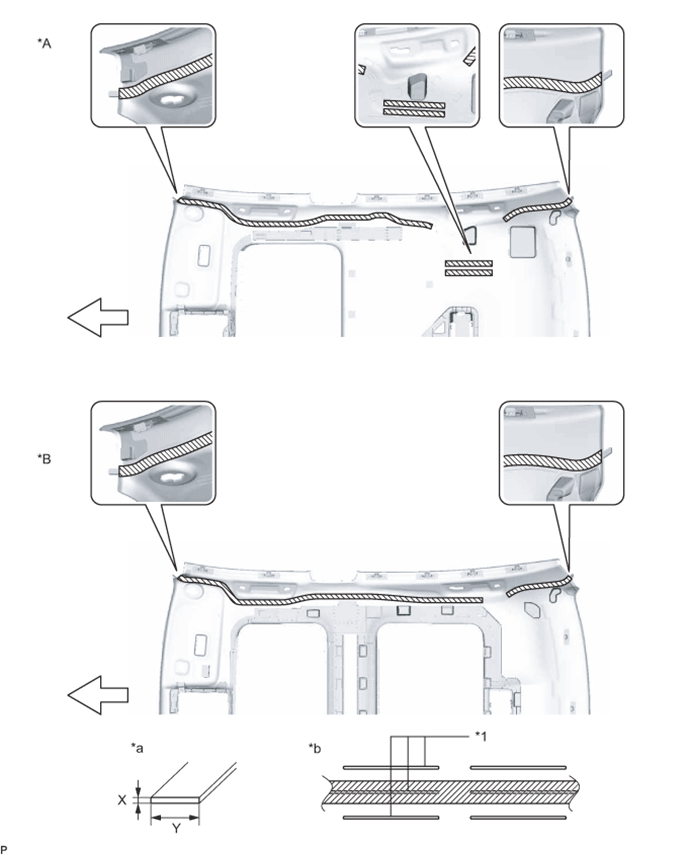
Text in Illustration *A for Standard *B for Glass Roof *1 Marking - - *a Double-sided Tape Size *b Tape Attachment Locations (Reference) 
Double-sided Tape - - 
Front - - Double-sided Tape Size Area Dimension X 1.0 mm (0.0394 in.) Y 10.0 mm (0.394 in.) -
Peel off the release paper from the double-sided tape.
-
Align the marking tape on the No. 2 antenna cord sub-assembly with the vehicle front end on the roof headlining assembly. (A)
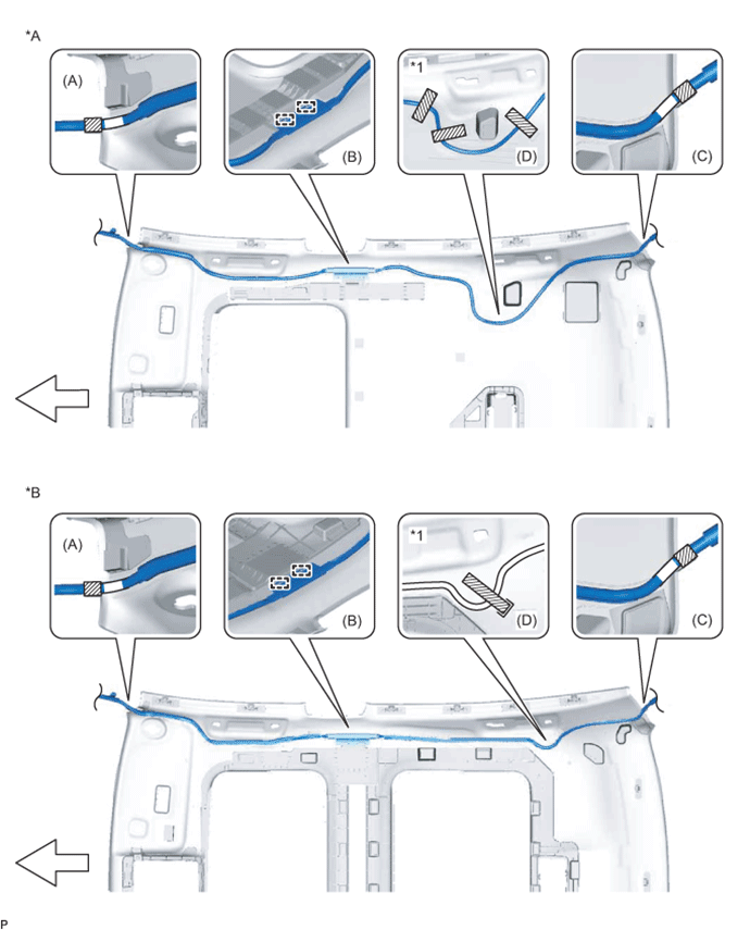
Text in Illustration *A for Standard *B for Glass Roof *1 Adjustment Area - - 
Marking Tape Adhesive Tape Front - - -
Engage the 2 guides. (B)
-
Align the marking tape on the No. 2 antenna cord sub-assembly with the vehicle rear end on the roof headlining assembly. (C)
-
Align the marking tape on the No. 2 antenna cord sub-assembly with the adjustment area on the roof headlining assembly. (D)
-
Attach the No. 2 antenna cord sub-assembly with the double-sided tape.
Note
-
Securely attach the No. 2 antenna cord sub-assembly.
-
If any of the No. 2 antenna cord sub-assembly is left loose, this will cause abnormal noise.
-
Make sure to attach the No. 2 antenna cord sub-assembly without leaving any of it loose.
Tech Tips
Secure the extra length of the No. 2 antenna cord sub-assembly in the adjustment area.
-
-
Apply adhesive tape by aligning it with the markings on the roof headlining as shown in the illustration.
-
-
INSTALL ROOF HEADLINING ASSEMBLY
-
INSTALL ANTENNA CORD SUB-ASSEMBLY (for LHD)
-
w/o Navigation System:
-
Engage the 6 clamps to install the antenna cord sub-assembly.
-
-
w/ Navigation System:
-
Engage the 7 clamps to install the antenna cord sub-assembly.
-
-
-
INSTALL ANTENNA CORD SUB-ASSEMBLY (for RHD)
-
Engage the 7 clamps to install the antenna cord sub-assembly.
-
-
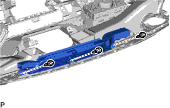
INSTALL NO. 3 HEATER TO REGISTER DUCT
-
Install the No. 3 heater to register duct with the 3 screws <D>.
-
-
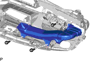
INSTALL DEFROSTER NOZZLE ASSEMBLY
-
Install the defroster nozzle assembly with the 3 screws <D>.
-
-
INSTALL NO. 1 DEFROSTER NOZZLE GARNISH
-
Engage the 8 guides and 9 claws to install the No. 1 defroster nozzle garnish as shown in the illustration.
-
-
INSTALL AUTOMATIC LIGHT CONTROL SENSOR
-
Connect the connector.
-
Engage the 2 claws to install the automatic light control sensor.
-
-
INSTALL NO. 2 SIDE DEFROSTER NOZZLE DUCT
-
Engage the 2 claws.
-
Install the No. 2 side defroster nozzle duct with the screw <D>.
-
-
INSTALL NO. 1 SIDE DEFROSTER NOZZLE DUCT
-
Engage the 2 claws.
-
Install the No. 1 side defroster nozzle duct with the screw <D>.
-
-
INSTALL INSTRUMENT PANEL SAFETY PAD ASSEMBLY