AUDIO AND VISUAL SYSTEM AVC-LAN Circuit
DESCRIPTION
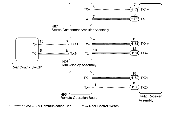
Each unit of the audio and visual system connected to the AVC-LAN (communication bus) transmits switch signals via the AVC-LAN communication.
If a short to +B or short to ground occurs in an AVC-LAN communication line, the audio and visual system will not function normally because communication is not possible.
WIRING DIAGRAM
INSPECTION PROCEDURE
Tech Tips
The radio receiver assembly is the master unit.
PROCEDURE
-
INSPECT RADIO RECEIVER ASSEMBLY
-
Remove the radio receiver assembly Click here.
-
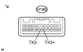
Text in Illustration *a Component without harness connected
(Radio Receiver Assembly)
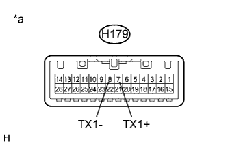
Text in Illustration *a Component without harness connected
(Radio Receiver Assembly)
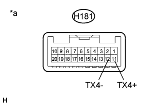
Text in Illustration *a Component without harness connected
(Radio Receiver Assembly)
Measure the resistance according to the value(s) in the table below.
Standard Resistance Tester Connection Condition Specified Condition H180-18 (TX2+) - H180-19 (TX2-) Always 60 to 80 Ω H179-7 (TX1+) - H179-8 (TX1-) Always 60 to 80 Ω H181-11 (TX4+) - H181-12 (TX4-) Always 60 to 80 Ω
NG 
REPLACE RADIO RECEIVER ASSEMBLY Click here
OK 
-
-
CHECK HARNESS AND CONNECTOR (AVC-LAN CIRCUIT)
-
Disconnect the H179, H180 and H181 radio receiver assembly connectors.
-
Disconnect the H87 stereo component amplifier assembly connector.
-
Disconnect the H93 multi-display assembly connector.
-
Disconnect the H95 remote operation board connector.
-
Disconnect the h2 rear control switch connector (w/ Rear Control Switch).
-
Measure the resistance according to the value(s) in the table below.
Standard Resistance Tester Connection Condition Specified Condition H179-7 (TX1+) - H87-8 (TX+) Always Below 1 Ω H179-8 (TX1-) - H87-7 (TX-) Always Below 1 Ω H181-11 (TX4+) - H93-7 (TX+) Always Below 1 Ω H181-12 (TX4-) - H93-19 (TX-) Always Below 1 Ω H180-18 (TX2+) - H95-10 (TX+) Always Below 1 Ω H180-19 (TX2-) - H95-11 (TX-) Always Below 1 Ω H93-6 (TX1+) - h2-15 (TX+)* Always Below 1 Ω H93-18 (TX1-) - h2-5 (TX-)* Always Below 1 Ω H179-7 (TX1+) - Body ground Always 10 kΩ or higher H179-8 (TX1-) - Body ground Always 10 kΩ or higher H181-11 (TX4+) - Body ground Always 10 kΩ or higher H181-12 (TX4-) - Body ground Always 10 kΩ or higher H180-18 (TX2+) - Body ground Always 10 kΩ or higher H180-19 (TX2-) - Body ground Always 10 kΩ or higher H93-6 (TX1+) - Body ground* Always 10 kΩ or higher H93-18 (TX1-) - Body ground* Always 10 kΩ or higher
-
*: w/ Rear Control Switch
-
NG
REPAIR OR REPLACE HARNESS OR CONNECTOR
OK
-
-
INSPECT MALFUNCTIONING PARTS
-
Disconnect and reconnect each slave unit one by one until the master unit returns to normal.
Tech Tips
-
Check all slave units.
-
If disconnecting a slave unit causes the master unit to return to normal, the slave unit is defective and should be replaced.
OK Master unit returns to normal. -
NG
REPLACE RADIO RECEIVER ASSEMBLY Click here
OK 
REPLACE MALFUNCTIONING PARTS
-