TILT AND TELESCOPIC MANUAL SWITCH INSTALLATION

-
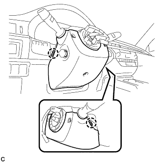
INSTALL TILT AND TELESCOPIC SWITCH
-
Engage the claw to install the tilt and telescopic switch.
-
Connect the connectors.
-
-
INSTALL LOWER STEERING COLUMN COVER
-
Engage the 2 claws to install the lower steering column cover.
-
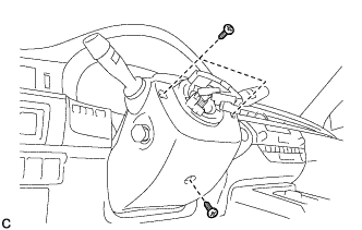
Install the 3 screws.
- Torque:
- 2.0 N*m { 20 kgf*cm, 18 in.*lbf }
-
-
ALIGN FRONT WHEELS FACING STRAIGHT AHEAD
-
INSPECT AND ADJUST SPIRAL CABLE WITH SENSOR SUB-ASSEMBLY
Note
Do not adjust the spiral cable with sensor sub-assembly with the battery connected and the engine switch on (IG).
-
Check that the engine switch is off.
-
Check that the cable is disconnected from the negative (-) battery terminal.
CAUTION:
Wait at least 90 seconds after disconnecting the cable from the negative (-) battery terminal to disable the SRS system.
-
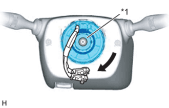
Check if the spiral cable with sensor sub-assembly is centered.
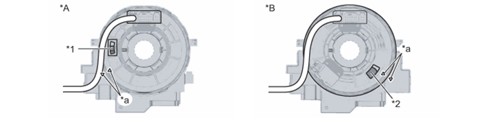
Text in Illustration *A w/o Steering Heater *B w/ Steering Heater *1 Colored Part *2 Flat Cable *a Alignment Mark - - Tech Tips
When the spiral cable with sensor sub-assembly is centered, the alignment marks are aligned and the colored part or flat cable shown in the illustration is visible.
-
If the spiral cable with sensor sub-assembly is not centered, center it.
Note
-
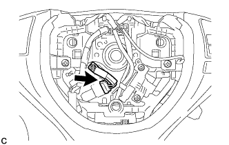
When rotating the spiral cable with sensor sub-assembly, make sure to push on the interlock indicated in the illustration to release the interlock mechanism.
-
Do not turn the spiral cable with sensor sub-assembly using the airbag wire harness.
-
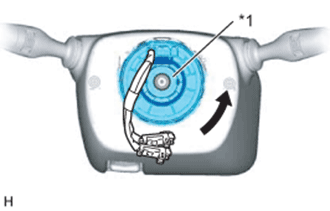
Text in Illustration *1 Interlock While pushing on the interlock indicated in the illustration, rotate the spiral cable with sensor sub-assembly counterclockwise slowly by hand until it stops.
-
Text in Illustration *1 Interlock While pushing on the interlock indicated in the illustration, rotate the spiral cable with sensor sub-assembly clockwise approximately 2.5 turns to the position where the colored part or flat cable is visible.
Tech Tips
The spiral cable with sensor sub-assembly will rotate approximately 2.5 turns to both the left and right from the center.
-
-
-
INSTALL STEERING WHEEL ASSEMBLY
-
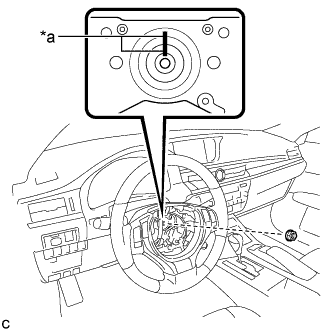
Text in Illustration *a Matchmark Install the steering wheel assembly aligning the matchmarks on the steering wheel assembly and steering main shaft.
-
Install the steering wheel assembly set nut.
- Torque:
- 50 N*m { 510 kgf*cm, 37 ft.*lbf }
-
w/ Steering Heater:
-
Connect the connector.
-
-
Connect the connectors to the spiral cable sub-assembly.
-
-
INSTALL HORN BUTTON ASSEMBLY