BRAKE BOOSTER (for RHD) REMOVAL

Note
Make sure to release vacuum from the brake booster assembly before removing the brake master cylinder sub-assembly from the brake booster assembly.
-
PRECAUTION
Note
After turning the engine switch off, waiting time may be required before disconnecting the cable from the negative (-) battery terminal, Therefore, make sure to read the disconnecting the cable from the negative (-) battery terminal notices before proceeding with work Click here.
-
REMOVE ENGINE ASSEMBLY WITH TRANSAXLE (for 2GR-FE)
-
RECOVER REFRIGERANT FROM REFRIGERATION SYSTEM (for 2AR-FE)
-
Start the engine.
-
Operate the cooler compressor under the conditions shown below:
Item Condition Indicator Operating Time 3 minutes or more - Temperature setting Max cool - Blower speed High 
Engine Idling - A/C switch On 
This causes most of the compressor oil from the various components of the A/C system to collect in the A/C compressor.
Tech Tips
It is not necessary to operate the cooler compressor if the A/C does not operate because of compressor lock, etc.
-
Stop the engine.
-
Recover the refrigerant from the A/C system using a refrigerant recovery unit.
Tech Tips
Use the refrigerant recovery unit in accordance with the manufacturer's instruction manual.
-
-
DISCONNECT CABLE FROM NEGATIVE BATTERY TERMINAL (for 2AR-FE)
Note
When disconnecting the cable, some systems need to be initialized after the cable is reconnected Click here.
-
REMOVE BRAKE MASTER CYLINDER SUB-ASSEMBLY
-
REMOVE FRONT BUMPER COVER
-
REMOVE RADIATOR SIDE DEFLECTOR RH
-
Disengage the 3 claws and guide to remove the radiator side deflector RH.
-
-
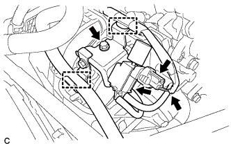
SEPARATE AIR CONDITIONER TUBE AND ACCESSORY ASSEMBLY
-
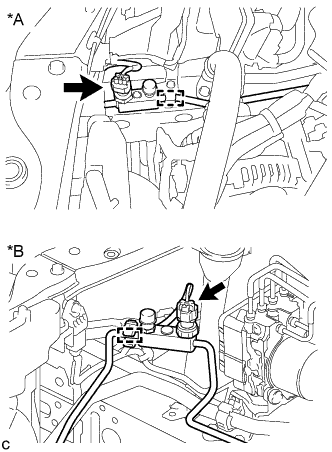
Text in Illustration *A for 2AR-FE *B for 2GR-FE Disconnect the pressure sensor connector and disengage the clamp.
-
Remove the bolt from the hook connector.
-
Turn the hook connector and separate the air conditioner tube and accessory assembly from the air conditioning unit.
Note
-
Do not deform the piping.
-
Do not damage the clamp.
-
-
Remove the bolt and separate the air conditioner tube and accessory assembly from the cooler condenser assembly.
Note
-
Do not deform the piping.
-
Do not damage the clamp.
-
-
Remove the 2 O-rings from the air conditioner tube and accessory assembly.
Note
Seal the openings of the disconnected parts using vinyl tape to prevent entry of moisture and foreign matter.
-
-
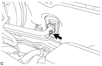
SEPARATE SUCTION PIPE SUB-ASSEMBLY
-
Disengage the clamp from the brake actuator bracket assembly.
-
Separate the clamp with suction pipe sub-assembly and air conditioner tube and accessory assembly from the No. 1 brake tube clamp.
-
Separate the suction pipe sub-assembly from the air conditioning unit.
Note
-
Do not deform the piping.
-
Do not damage the clamp.
-
-
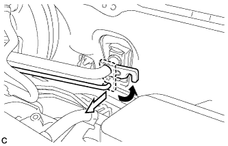
Remove the O-ring from the suction pipe sub-assembly.
Note
Seal the openings of the disconnected parts using vinyl tape to prevent entry of moisture and foreign matter.
-
-
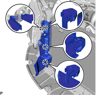
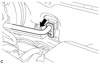
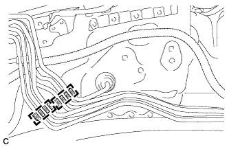
REMOVE NO. 1 BRAKE TUBE CLAMP
-
Disengage the clamp to separate the brake lines.
Note
Do not kink or damage the brake lines.
-
Remove the bolt and No. 1 brake tube clamp from the vehicle body.
-
-
REMOVE BRAKE LINE
-
Using a union nut wrench, disconnect the 2 brake lines from the brake actuator assembly.
-
Remove the 2 clamps to make the 2 brake lines free.
Note
-
Do not kink or damage the brake lines.
-
Do not allow any foreign matter such as dirt or dust to enter the brake lines from the connecting parts.
-
-
-
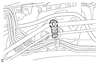
REMOVE VACUUM SWITCHING VALVE ASSEMBLY (for 2AR-FE)
-
Disconnect the union to check valve hose and wire harness clamp.
-
Disconnect the 2 vacuum hoses and connector.
-
Remove the bolt and vacuum switching valve assembly.
-
-
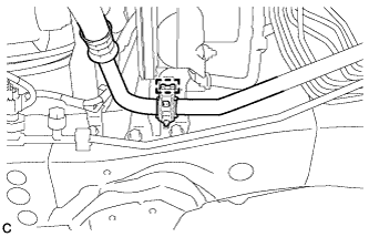
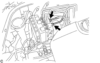
DISCONNECT UNION TO CHECK VALVE HOSE (for 2AR-FE)
-
Slide the clip and disconnect the union to check valve hose from the brake booster assembly.
-
-
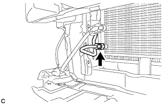
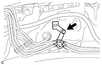
REMOVE PUSH ROD PIN
-
Remove the clip and push rod pin.
-
-
REMOVE BRAKE BOOSTER ASSEMBLY
-
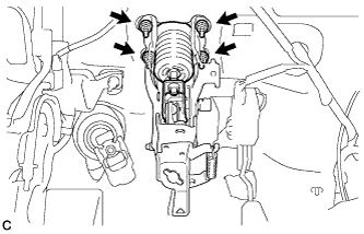
Remove the 4 nuts and brake booster assembly from the vehicle body.
Note
Do not kink or damage the brake lines, air conditioner tube and accessory assembly or suction pipe sub-assembly.
-
-
REMOVE BRAKE BOOSTER GASKET
-
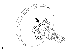
Remove the brake booster gasket from the brake booster assembly.
-
-
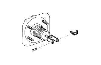
REMOVE BRAKE MASTER CYLINDER PUSH ROD CLEVIS
-
Loosen the lock nut and remove the brake master cylinder push rod clevis and lock nut.
-
-
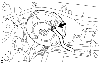
REMOVE BRAKE VACUUM CHECK VALVE ASSEMBLY
-
Remove the brake vacuum check valve assembly from the brake booster assembly.
-
-
REMOVE CHECK VALVE GROMMET
-
Remove the check valve grommet from the brake booster assembly.
-