BRAKE MASTER CYLINDER (for LHD) INSTALLATION

-
INSTALL BRAKE MASTER CYLINDER O-RING
-
Install a new brake master cylinder O-ring to the brake master cylinder sub-assembly.
-
-
INSTALL BRAKE MASTER CYLINDER SUB-ASSEMBLY
Note
When installing a new brake master cylinder sub-assembly, remove the protectors from the master cylinder piston and outlet ports.
-
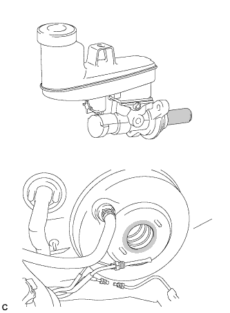
Apply a light layer of a grease enclosed with a new brake master cylinder sub-assembly or lithium soap base glycol grease to the circumference of the brake master cylinder sub-assembly and inner surface of the brake booster assembly as shown in the illustration.
Text in Illustration 
Apply Grease -
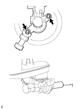
Text in Illustration *1 Master Cylinder Piston Install the brake master cylinder sub-assembly and front brake tube way to the brake booster assembly with the 2 nuts.
- Torque:
- 13 N*m { 130 kgf*cm, 9 ft.*lbf }
Note
-
Do not hold the brake master cylinder sub-assembly by the master cylinder piston. Hold the brake master cylinder sub-assembly by its body or its reservoir when carrying it.
-
Do not pull out the master cylinder piston.
-
Do not strike or pinch the master cylinder piston, or cause any damage to the master cylinder piston by any other means.
-
When installing the brake master cylinder sub-assembly to the brake booster assembly, or when removing the brake master cylinder sub-assembly from the brake booster assembly, make sure that the brake master cylinder sub-assembly is kept horizontal or its tip faces downward (the master cylinder piston faces upward) to prevent the master cylinder piston from falling out.
-
Do not allow any foreign matter to contaminate the master cylinder piston. If any foreign matter gets on the master cylinder piston, remove it by using a piece of cloth and then apply an even layer of lithium soap base glycol grease around the circumference (sliding part) of the master cylinder piston.
-
Do not use any other types of grease.
-
Do not kink or damage the brake lines.
-
Do not allow brake lines to twist or interfere with other parts or the vehicle body during flexible hose tightening.
-
Do not allow any foreign matter such as dirt or dust to enter the brake lines.
-
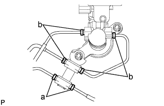
Using a union nut wrench, connect the 6 brake lines and install the brake master cylinder to way tube to the brake master cylinder sub-assembly.
- Torque:
- a
- 15 N*m { 155 kgf*cm, 11 ft.*lbf }
- b
- 20 N*m { 199 kgf*cm, 14 ft.*lbf }
Note
-
Do not kink or damage the brake lines.
-
Do not allow brake lines to twist or interfere with other parts or the vehicle body during flexible hose tightening.
-
Do not allow any foreign matter such as dirt or dust to enter the brake lines.
-
Use the formula to calculate special torque values for situations where the union nut wrench is combined with a torque wrench Click here.
-
Connect the reservoir level switch connector and engage the clamp.
-
-
BLEED BRAKE SYSTEM
-
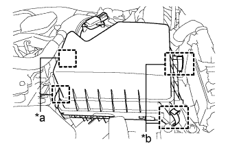
INSTALL AIR CLEANER CASE SUB-ASSEMBLY (for 2AR-FE)
-
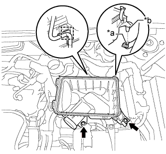
Text in Illustration *a Hole *b Projection Insert the projection of the air cleaner case sub-assembly into the hole of the No. 2 air cleaner bracket as shown in the illustration.
-
Install the 2 bolts.
- Torque:
- 5.0 N*m { 51 kgf*cm, 44 in.*lbf }
-
Connect the wire harness clamp.
-
-
INSTALL AIR CLEANER FILTER ELEMENT SUB-ASSEMBLY (for 2AR-FE)
-
INSTALL AIR CLEANER CAP SUB-ASSEMBLY (for 2AR-FE)
-
Text in Illustration *a Hinge *b Clamp Connect the 2 hinges of the air cleaner cap sub-assembly.
-
Install the air cleaner cap sub-assembly with the 2 clamps.
-
Connect the air cleaner cap sub-assembly to the throttle with motor body assembly the hose clamp.
-
Connect the ventilation hose to the cylinder head cover.
-
Install the fuel vapor feed hose to the air cleaner hose.
-
Connect the mass air flow meter connector and 2 wire harness clamps to the air cleaner cap sub-assembly.
-
Connect the vacuum switching valve assembly to the air cleaner cap sub-assembly.
-
-
INSTALL INLET AIR CLEANER ASSEMBLY (for 2AR-FE)
-
Install the inlet air cleaner assembly with the 2 bolts.
- Torque:
- 8.0 N*m { 82 kgf*cm, 71 in.*lbf }
-
-
INSTALL AIR CLEANER CASE SUB-ASSEMBLY (for 2GR-FE)
-
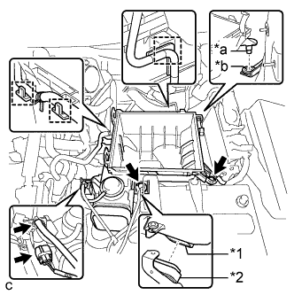
Text in Illustration *1 Air Cleaner Case Sub-assembly *2 Inlet No. 1 Air Cleaner *a Projection *b Hole Install the air cleaner case sub-assembly to the inlet No. 1 air cleaner.
-
Insert the projection of the air cleaner case sub-assembly to the hole of the No. 2 air cleaner bracket as shown in the illustration.
-
Tighten the 2 bolts.
- Torque:
- 5.0 N*m { 51 kgf*cm, 44 in.*lbf }
-
Connect the 3 wire harness clamps, connector, vacuum hose and No. 1 fuel vapor feed hose.
-
-
INSTALL AIR CLEANER FILTER ELEMENT SUB-ASSEMBLY (for 2GR-FE)
-
INSTALL AIR CLEANER CAP SUB-ASSEMBLY (for 2GR-FE)
-
Connect the air cleaner cap sub-assembly to the throttle with motor body assembly with the hose clamp.
-
Install the air cleaner cap sub-assembly to the air cleaner case with the 2 clamps.
-
Connect the 3 hoses.
-
Connect the ventilation hose.
-
Connect the mass air flow meter connector and wire harness clamp.
-
-
INSTALL INLET NO. 2 AIR CLEANER (for 2GR-FE)
-
Install the inlet No. 2 air cleaner to the air cleaner case sub-assembly with the 2 bolts.
- Torque:
- 8.0 N*m { 82 kgf*cm, 71 in.*lbf }
-
Connect the 2 wire harness clamps and vacuum hose clamp.
-
-
INSTALL COOL AIR INTAKE DUCT SEAL
-
Install the cool air intake duct seal with the 9 clips.
-
-
INSTALL FRONT OUTER COWL TOP PANEL SUB-ASSEMBLY
-
Install the front outer cowl top panel sub-assembly with the 10 bolts.
- Torque:
- 10 N*m { 102 kgf*cm, 7 ft.*lbf }
-
Engage the 2 clamps to install the wire harness to the front outer cowl top panel sub-assembly.
-
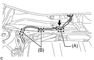
Connect the connector to install the wire harness to the front outer cowl top panel sub-assembly.
-
Engage the 2 clamps (B).
-
w/ Wiper Deicer System:
Engage the clamp (A).
-
-
INSTALL WINDSHIELD WIPER MOTOR AND LINK ASSEMBLY